Transilluminator operation – UVP High Performance UV Transilluminators User Manual
Page 4
High Performance UV Transilluminators
Page 4
2UV High Performance Transilluminators
Units are equipped with an electronic ballast and 25 watt tubes. Four tubes of each wavelength are
installed. These models have a single intensity. The physical dimensions of all models are:
Width: 14” x Depth: 11” x Height: 4.8” (356 x 279 x 122mm)
Part
Wave-
No. of
Intensity
Model
Number
length
Volts/Hz
Filter Size
Tubes
Style
TFML-20
95-0431-01 302/365nm
100-115V/60Hz 20 x 20 cm
4 x 25W
Single
TFML-20
95-0431-02 302/365nm
230V/50Hz
20 x 20 cm
4 x 25W
Single
TFML-26
95-0425-01 302/365nm
100-115V/60Hz 21 x 26 cm
4 x 25W
Single
TFML-26
95-0425-02 302/365nm
230V/50Hz
21 x 26 cm
4 x 25W
Single
TFML-30
95-0432-01 302/365nm
100-115V/60Hz 25 x 30 cm
4 x 25W
Single
TFML-30
95-0432-02 302/365nm
230V/50Hz
25 x 30 cm
4 x 25W
Single
TFML-40
95-0436-01 302/365nm
100-115V/60Hz 20 x 40 cm
4 x 25W
Single
TFML-40
95-0436-02 302/365nm
230V/50Hz
20 x 40 cm
4 x 25W
Single
Transilluminator Operation
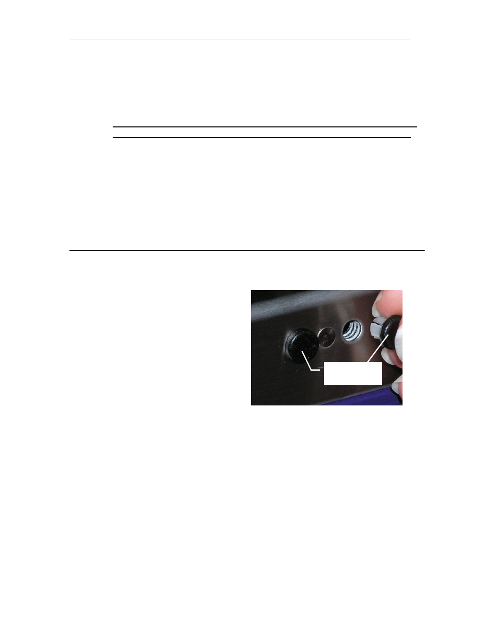
Safety Precautions
When the UV Blocking Cover is not being
used, UV light may escape through the
holes dedicated to accepting the bracket
pins of the UV Blocking Cover.
Remove the black safety plugs from
their package
Insert the safety plugs through the
holes as shown.
Set-Up
Place the transilluminator on a level work surface. Be sure that an air space exists
around the bottom of the work surface. This space allows for the proper air
circulation through the unit.
Plug the female end of the power cord into the transilluminator. For 230 volt
models, or those requiring special power cord connectors, ensure that the proper
configuration of male connector or plug is properly connected to the power cord.
Plug the male end of the power cord into a properly grounded electrical outlet. The
proper voltage of the transilluminator is found on the product information label. If
using the transilluminator with an imaging system, a jumper cable is required for
connecting to the darkroom. Refer to the imaging system documentation for
additional instructions.
The transilluminator may be equipped with a UV Blocking Cover. Remove the
brown protective paper from the cover. Insert the bracket pins on the cover into the
Safety Plug