Cosine response, Summary – UVP UVX Radiometer User Manual
Page 25
UVX Radiometer
25
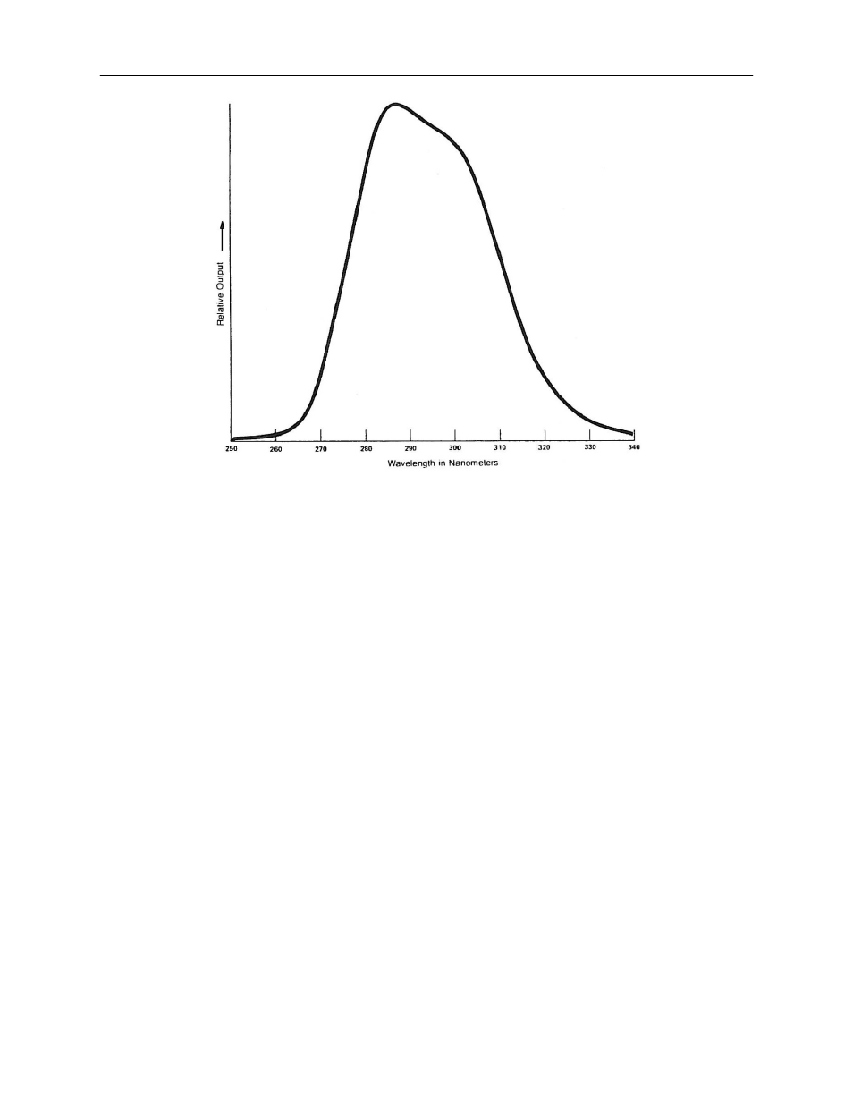
Figure 15: Continuous Emitter, 285nm Phosphor Coated UV Lamp
Cosine Response
For a sensor to accurately measure irradiance, it is necessary that it preserve a cosine relationship which
depends on the angle of incident radiation. This relationship is a function of the projected area of the
sensor, as seen in a plane normal to the incident light. See Figure 17.
Since the projected area is proportional to the power that the sensor intercepts, the irradiance measured
for radiation incident at an angle O will be given by 1
0
cos O. 1
0
is the irradiance that would be measured if
the sensor were pointed directly toward the incident region. Sensors that "weigh" their response in this
manner are said to be cosine corrected.
The Polar Plot in Figure 18 has been drawn from the curve of Figure 10 to show how the UVX sensor
compares to the perfect cosine response. The sensor is identified by the broken curve in the figure. The
solid curve, also shown, identifies a perfect cosine response. The UVX Series Sensors offer this same
high degree of cosine corrected response.
Summary
Many parameters affect radiant incidence measurements. These parameters can, however, be divided
into two classes; those which are a function of the sensor and those which are not. The most important
specifications of a sensor design have been discussed above. They are: spectral response, field of view,
distance and cosine response.