Repairs and replacement parts, Switch replacement procedures, Replacement parts – UVP EC3 Imaging System User Manual
Page 9
Switch Replacement
Procedures
Repairs and Replacement Parts
For technical assistance, contact UVP’s offices listed in the
Technical Assistance section. To order replacement parts, contact
UVP’s Customer Service Department at the same locations.
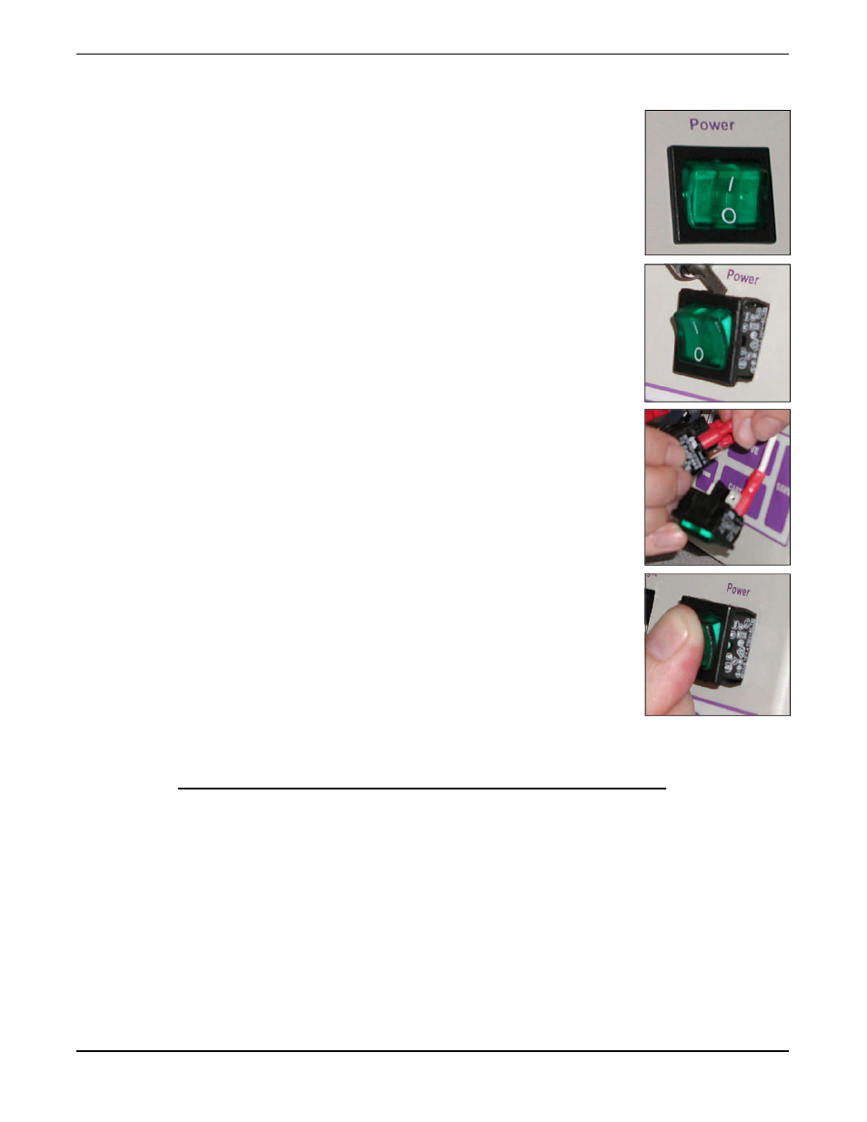
Switch Replacement Procedures
The darkroom and transilluminator use the same power switch. To
replace the power switch in the darkroom or transilluminator:
1.
Unplug the darkroom and/or transilluminator from the power
source prior to removing the power switch.
2.
To remove the power switch from the unit, use a thin flat head
screw driver to pry the switch out from housing. Be careful not to
scratch the paint of the darkroom or transilluminator in the pro-
cess.
3.
Once the switch is removed, you will see a number of connector
wires plugged into the back of it. Normally there are two black
and two white wires, with some exceptions. Pull one wire out of
the old switch and put it into the same connector location on the
new switch. Continue this process for each wire until all are
connect to the new switch.
4.
Push the new switch back into its position.
Replacement Parts
To order replacement parts for the EC3 Imaging System, contact
UVP’s offices. Contact information is listed on the next page.
Part Description
Part Number
Qty.
Tube, 8 watt, fluorescent, cool white
34-0056-01
2
Tube, 8 watt, 365nm UV longwave
34-0006-01
2
Tube, 8 watt, 254nm UV germicidal
34-0007-01
2
Cable and connector wall plug, 115V and 100V
58-0085-01
1
Cable and connector wall plug, 230V
58-0085-03
1
Power Switch
53-0024-01
1
7
EC3 Imaging System