Installation, Wiring diagrams – Regency Energy U32E Medium Gas Insert User Manual
Page 31
U32E-5 FPI Direct Vent Gas Insert
31
INSTALLATION
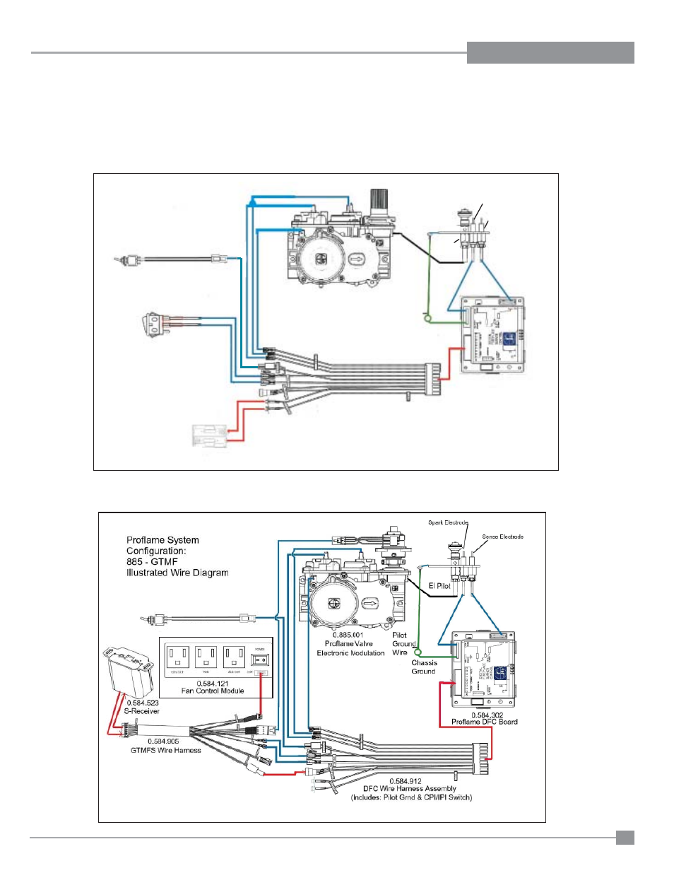
WIRING DIAGRAMS
This heater does not require a 120V A.C. supply for operation. In case of a power failure, the burner switch and the optional remote control/
thermostat will continue to operate. However, a 120V A.C. power supply is needed for the fan/blower operation.
Caution: Ensure that the wires do not touch any hot surfaces and are away from sharp edges.
SureFire™ Switch
Proflame System
886 ON/OFF Stand Alone
Illustrated Wire Diagram
Surefire Switch
(IPI / CPI)
Standard Main ON/OFF
Switch or Optional Wall Switch
Battery Holder
Pilot Ground Wire
Chassis Ground
EI Pilot
Sense Electrode
Spark Electrode
DFC Wire Harness Assembly
Proflame DFC Board
886 Proflame Valve
Note: 4 AA batteries must be in-
stalled to operate the burner switch.
Do not use a 9 volt battery.
IMPORTANT:
If the optional remote control is used, the AA batteries normally installed into the battery holder must be removed. The AA batteries in the
receiver now operate the unit. Having AA batteries in both the battery holder and receiver will damage the gas valve.
- Alterra CI1200 Small Wood Insert (32 pages)
- Alterra CS1200 Small Wood Stove (32 pages)
- Alterra CS2400 Medium Wood Stove (32 pages)
- Bellavista B36XTCE Medium Gas Fireplace (72 pages)
- Bellavista B36XTE Medium Gas Fireplace (72 pages)
- Bellavista B41XTCE Large Gas Fireplace (68 pages)
- Bellavista B41XTE Large Gas Fireplace (64 pages)
- CI2600 Large Wood Insert (40 pages)
- Classic C34 Small Gas Stove (44 pages)
- Classic F3100 Large Wood Stove (28 pages)
- Classic F2400 Medium Wood Stove (28 pages)
- Classic F5100 Extra Large Wood Stove (36 pages)
- Classic H2100 Hearth Heater Wood Insert (24 pages)
- Classic I1200 Small Wood Insert (24 pages)
- Classic I2400 Medium Wood Insert (20 pages)
- Classic R90 Large Wood Fireplace (Canadian Edition) (40 pages)
- Classic R90 Large Wood Fireplace (US Edition) (36 pages)
- Energy U21 Small Gas Insert (40 pages)
- Energy U31 Medium Gas Insert (36 pages)
- Energy U32 Medium Gas Insert (44 pages)
- Excalibur E33 Large Gas Insert (44 pages)
- Excalibur P90 Medium Gas Fireplace (56 pages)
- Greenfire GF55 Medium Pellet Insert (16 pages)
- Hampton GC60 Large Pellet Stove OWNER'S MANUAL (18 pages)
- Hampton GC60 Large Pellet Stove TECHNICAL MANUAL (32 pages)
- Hampton GCI60 Large Pellet Insert OWNER'S MANUAL (18 pages)
- Hampton GCI60 Large Pellet Insert TECHNICAL MANUAL (34 pages)
- Hampton H15 Small Gas Stove (48 pages)
- Hampton H200 Medium Wood Stove (36 pages)
- Hampton H27 Medium Gas Stove (48 pages)
- Hampton H300 Large Wood Stove (36 pages)
- Hampton H35 Large Gas Stove (48 pages)
- Hampton HI200 Small Wood Insert (24 pages)
- Hampton HI300 Medium Wood Insert (32 pages)
- Horizon HZ30E Small Gas Fireplace (64 pages)
- Horizon HZ33CE Small Gas Fireplace (60 pages)
- Horizon HZ40E Medium Gas Fireplace (68 pages)
- Horizon HZ42STE Medium Gas Fireplace (60 pages)
- Horizon HZ54E Large Gas Fireplace (68 pages)
- Horizon HZ965E Large Gas Fireplace (68 pages)
- Horizon HZI234E Small Gas Insert (52 pages)
- Horizon HZI390EB Medium Gas Insert (60 pages)
- Horizon HZI540EB Large Gas Insert (56 pages)
- Horizon HZO42 Outdoor Gas Fireplace (44 pages)
- Liberty L234 Small Gas Insert (44 pages)