Installation, Stove assembly prior to installation – Regency Classic F5100 Extra Large Wood Stove User Manual
Page 7
F5100 Regency Freestanding Woodstove
7
INSTALLATION
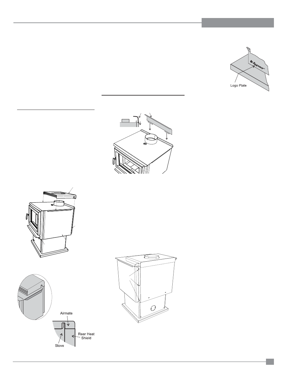
Side View
Rear Heat Deflector
Screws
Diagram 2
Diagram 3
STOVE ASSEMBLY
PRIOR TO
INSTALLATION
The F5100 unit requires the pedestal attached
to the base. The F5100 stove requires either
the Airmate or Rear Heat Defl ector on top of
the stove. Clearances to combustible materials
vary depending on whether the airmate or rear
heat defl ector is installed, so be sure to check
the Minimum Clearances, Installation section.
Airmate Assembly for F5100
1. The airmate sits on top of the stove with
the slots in the sides fi tting over the curved
defl ector on the rear stove top. See diagram
1. Discard the Rear Heat Defl ector that is
supplied with the unit, it is not required if the
airmate is installed.
2. Center the airmate and push it forward to the
front of the stove. The back of the airmate
should be level with the back and sides of
the rear heat shield. See Diagrams 2 & 3.
Rear Heat Defl ector
Assembly for F5100
The rear heat defl ector is supplied with the stove
and must be installed unless the optional airmate
has been selected. It stops the heat radiated
from the fl ue collar from overheating the rear
wall. The rear heat defl ector is installed on top of
the rear heat shield, as shown in Diagram 4.
Side Shield Adjustment
The left and right side shields are lowered for ship-
ping and handling. It allows for a handhold on the
top of the stove. Before placing in the Step Stove
in its fi nal position, the side shields must be raised.
Loosen the screws on the rear on the stove (3 per
side), slide the side panel up as far as possible and
then secure by tightening the screws.
1. Push
the
Regency logo
into the two
holes in the
front bottom left
corner of the
pedestal cover
plate.
Note: Any paint touch up should be done prior
to placing logo on pedestal.
2. If not using ash drawer, then cover plate must be
installed.
Airmate
Rear Heat
Shield
Side
Shield
Stove
Diagram 1
Diagram 4
Diagram 5
Diagram 6
Logo Installation