Schwank IT(U) User Manual
Page 13
GP-MSEM-BX-06A
SEM(U) / IT(U) Manual
RD: Aug 2006
RL: 06A
KH
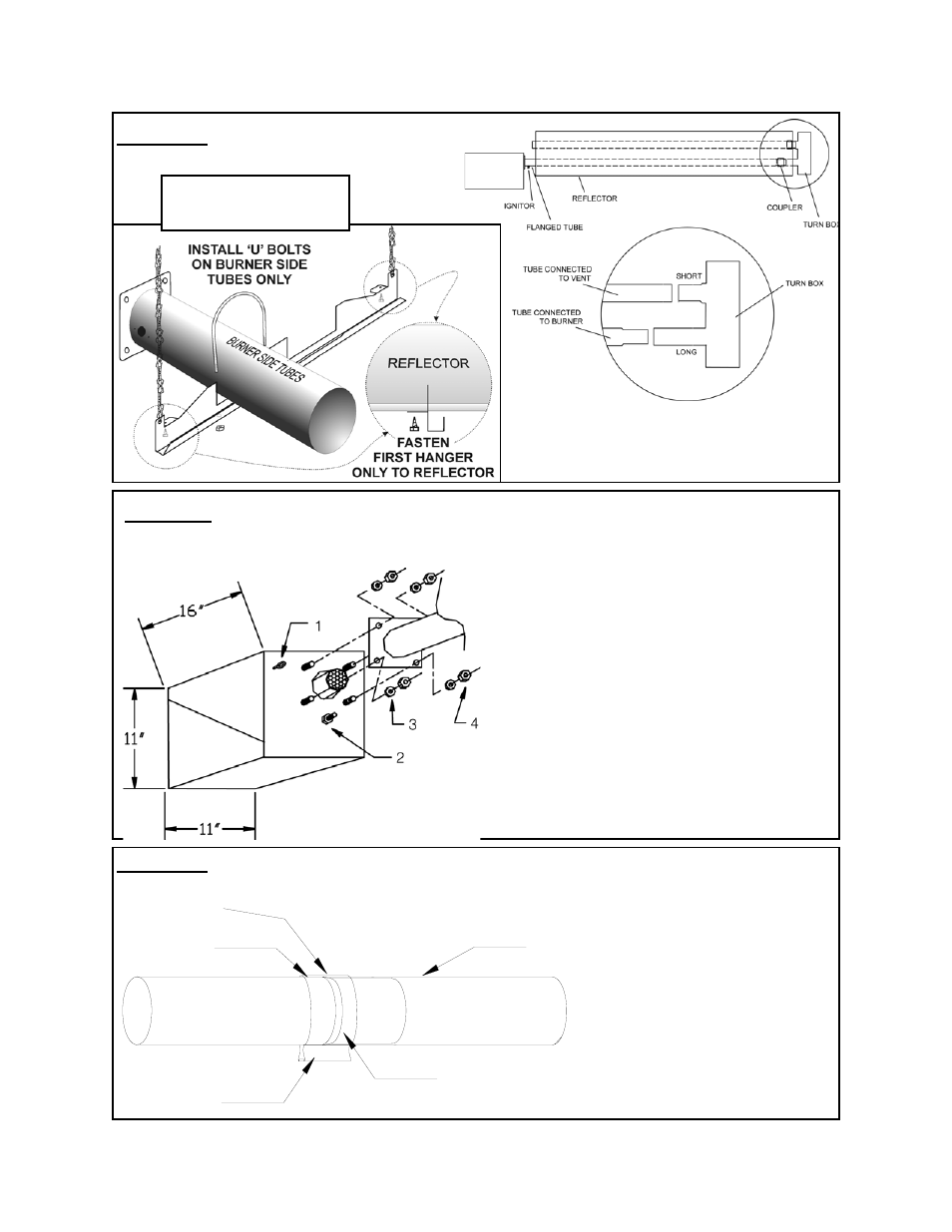
FIGURE 5 ‘U’ TUBE MODELS
TURN BOX
FIGURE 5B
‘U’ TUBE HANGER
FIGURE 5A
3
2
1
4
5
FIGURE 7 COUPLER KIT
(also see Fig. 8 for 175 / 200,000 models)
1 Tube
2 Tube Coupler
3 Swaged section of tube
4 Point at which the Swaged tube
slides into other section of tube
5 Once the two tubes are joined
together, place the centre of
the Coupling over the line of
the joint and tighten.
1
Eye Hook
2
Fifth Nut (Holds Inner Burner to Housing)
3
Lock Washers (4) Four
4
Nuts (4) Four Note: Nuts may be shipped
c/w lock-washers as one piece
•
Insert four burner bolts through the tube
flange, secure tightly with lock washers and
nuts.
•
Note: A Flange Gasket is not required for
this application
•
Do not loosen or remove fifth nut (#2) di-
rectly below burner cup
•
Secure suspension chain to eye hook in or-
der to stabilize burner
•
Align the four burner bolts through flange
on tube, secure tightly with lock washers
and nuts
FIGURE 6
BOLTING BURNER TO FLANGED TUBE
Page 9