Important: * (s – Schwank IT(U) User Manual
Page 10
GP-MSEM-BX-06A
SEM(U) / IT(U) Manual
RD: Aug 2006
RL: 06A
KH
7. SYSTEMS INCORPORATING 90° ELBOWS
The 90° elbows are shipped as a kit with one
clamp and two end caps to close off the re-
flector ends each side of the elbow (s). The
Reflectors must be secured with four screws
to each of the end caps. (see FIG 10)
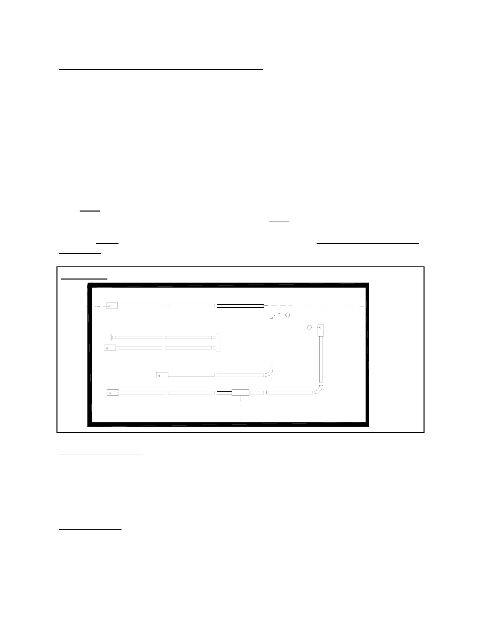
FIGURE 2 SYSTEM CONFIGURATIONS
System Configuration
1
Straight line
2
“U” tube with Turn Box
3
“L” tube with 90
0
elbow kit
4
Twinned tubes into common TEE flue vent
* Note: Both heaters must be connected
with a single common thermostat
Venting Options
A Flue vent through wall 4”
B Flue vent through wall or roof 6”
C Flue vent through roof
D Flue vent into building, exhaust fan inter
locked with heater
E Combustion air intake from outside
through wall.
F Combustion air intake from outside
through roof
G Combustion air intake from inside
building
IMPORTANT: * (S
TRAIGHT
T
UBE
M
ODEL
O
NLY
) *
E
A
G
4
3
G
G
D
2
1
F
C
Model SEM / IT 100 x 20’ must be installed as a “straight system” with no elbows al-
lowed at the 10’ location. On Models SEM / IT, 175 a minimum of 30´ of straight radiant
tube must be connected to the burner before any elbow. On Models SEM / IT 155, 130,
and 110 a minimum of 20´ of straight radiant tube must be connected to the burner be-
fore any elbow. And on Models SEM / IT 80 and 60, a minimum of 10´ of straight radi-
ant tube must be connected to the burner before any elbows.
Not applicable to SEMU/
ITU model
The SEM / IT Series radiant tube heater can
be installed in configurations as illustrated in
Fig:2 (below) with a maximum of two 90°
elbows per heater. The use of radiant elbows
reduces the total maximum vent allowable.
(See SECTION: 11) Flue Venting.
Page 6
B