Schwank IT(U) User Manual
Page 12
GP-MSEM-BX-06A
SEM(U) / IT(U) Manual
RD: Aug 2006
RL: 06A
KH
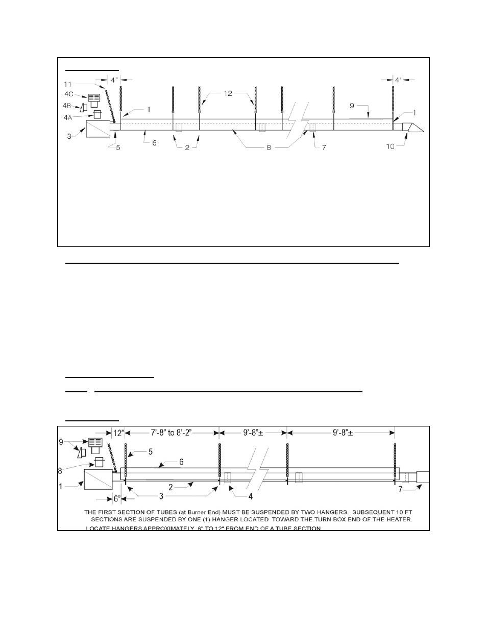
* Distances shown are recommendations and may be varied to match field requirements.
9– Reflector
10- Flue Vent terminal
11- Burner Support Chain
12- Hanger Support Chains
4C - JA-0528-XX 4” Roof Cap
5- Sight Glass
6- Aluminized Tube with Flange
7– Tube Coupler
8- Steel Tube(s)
1- End Cap
2- Wire Hanger
3- Burner Assembly
4- Combustion Air Intake Options
4A—JS-0532-SE 4” Intake Adapter
4B - JS-0532-VC 4” Wall Cap
4
”
SUSPEND ALL TUBES BY TWO (2) HANGERS PER 10’ LENGTH, MOUNTED APPROX. 6” to 12” IN FROM EACH TUBE END.
1.
Burner
2.
Tube with Flange
3.
‘U’ Tube Hanger
4.
Tube Coupler
5.
Suspension Chain
6.
Reflector
7.
Turn Box
8.
JS-0532-SE 4” Fresh Air Adapter
9.
JS-0532-VC 4” Wall Cap
or JA-0528-XX 4” Roof Cap
FIGURE 4A SEM / IT MODELS TYPICAL HANGER & SUPPORT SPACING
FIGURE 4B SEMU / ITU MODELS TYPICAL HANGER & SUPPORT SPACING
9.1. SEMU / ITU ’U’ TUBE SYSTEM ~ BURNER AND TUBE INSTALLATION
SEMU / ITU: With all hangers aligned and suspended at the same height, install first alumin-
ized tube section, onto the first two hangers. Fasten tube to hangers with ‘U’ bolts. All tubes on
the burner-side of the heater are bolted to the hangers - Tubes on vent-side rest in the hanger
notch and do not fasten. SEE FIGURES 4B & 5
Bolt burner to flange on first tube section, SEE FIGURE 6. Subsequent lengths of tube can then
be installed, by joining them together one inside the other and locking the joints using the alu-
minized steel coupler. SEE FIGURE 7.
Note: If angle mounting a ‘U’ Tube model, the vent side must always be in the upper location.
IMPORTANT NOTE: Models with inputs 175,000 & 200,000 refer to section 9C.
Note: Turbulators are ALWAYS installed at the vent end of the heater .
Page 8