Operation, Display screens – SATEC PM135 Quick Start User Manual
Page 3
PM135 QuickStart
www.satec-global.com
OPERATION
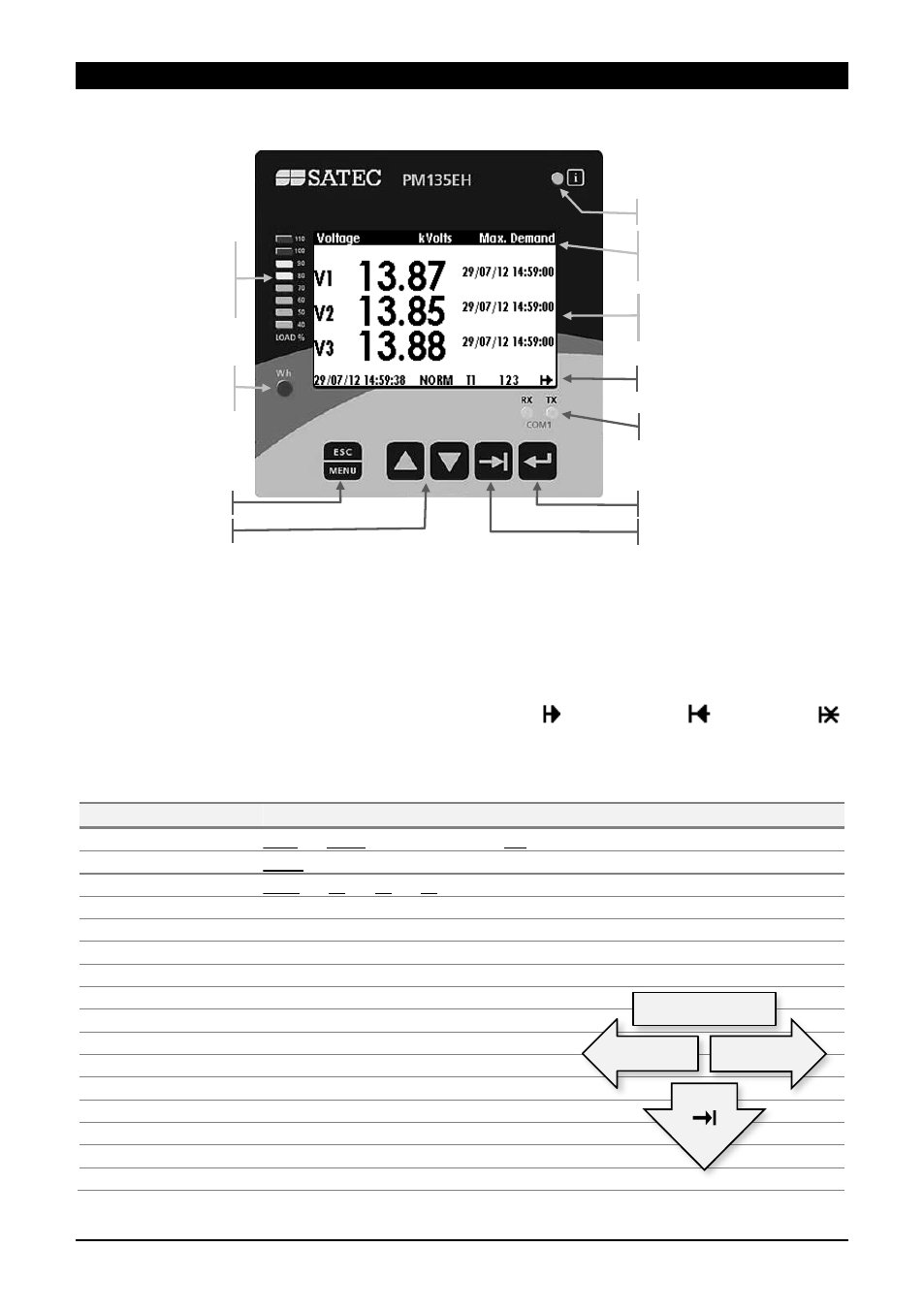
The PM135 is operated using the front panel which consists of an LCD display, 12 LEDs and five
keys as shown below:
Status Line
Date, time, operation mode, current tariff (T1
T8), phase indicators and power flow direction.
Operation modes: NORM and TEST. In the TEST mode the energy registers are not
accumulated and the calibration led is 10 times faster (10 pulses per Wh or varh).
Phase indication is on when voltage is ok, blinking when below voltage dip set value or marked
as “-“ when below the interruption set value.
Power flow direction: Normal flow (generation to load) – , reverse flow –
or no load –
Display Screens
Group ( to change)
Screens ( to go right, to go left). Underlined = included in Auto Scroll
Voltages
V L-L
//
V L-N
//
THD
//
Ue
//
Hz
//
Phase
//
Demand
Currents
Amps
//
THD
//
TDD
//
K Factor
//
Unbalance
//
Demand
Powers
Total
//
L1
//
L2
//
L3
//
Import Demand
//
Export Demand
Demands
P Import
//
P Export
//
Amps
//
Volts
Min/Max
V L-L
//
V L-N
//
Amps
//
I neutral
//
P
//
PF
//
Hz
Energy
Import
//
Export
TOU (Import, Export)
Reg#1
//
Reg#2
Harmonics
#3
//
#5
//
#7 … #39
Spectrum
V1
//
V2
//
V3
//
I1
//
I2
//
I3
Waveform
L1
//
L2
//
L3
Phasor
Digital I/O
Diagnostic
Alarms
Basic Settings
Page1
//
Page2
Device Info
Info
//
Com
Diagnostic LED. Off = OK
Load bar graph
(full load according to
CT or in Display Setup)
Title (displayed value, units,
phase/s)
Main display
(real time, min, max)
Calibration LED
(1 pulse/Wh or Varh)
Communication Indication
Status line (see below)
Scroll up/down
Select / Enter
TAB - Change screen,
submenu etc.
Menu / Escape
Press
Press
Press
Navigation