S&S Cycle Crankcase for Harley-Davidson Twin Cam 88 Engines User Manual
Page 3
To check clearance perform following steps:
1. Assemble case halves using case bolts. Tighten to snug.
Torquing bolts to final specification is not necessary.
2. Clean frame engine mounts and carefully remove any
irregularities from mounting surfaces. Also inspect crankcase
mounting bosses for burrs.
3. Position case assembly in frame.
4. Install engine mounting bolts in motor mounts, and check
clearance between mounting bosses on cases and frame and
any other areas where frame and cases may contact each other.
Bolts may be difficult to install if contact is severe.
5. If cases contact frame, remove them and relieve just enough
material in offending area to provide clearance.
6. Place cases in frame, install one rear mounting bolt and snug
nut.
7. Measure gap between crankcase mounting bosses and frame
motor mounts with feeler gauge to determine if shimming is
required.
8. If gap exists, fabricate shim just thick enough to fill gap.
9. Install opposite corner shim and mounting bolt and nut, and
tighten identical to other bolt.
10. Check other corners with feeler gauge to confirm thickness
required is same as before. If not, determine cause and correct.
3. Pre-Assembly Cleaning
Clean crankcases in hot soapy water or solvent to remove any
dirt or contamination which may have been introduced during
shipping, handling, or set-up. Dry components and check
passages with compressed air. Improper alignment of engine and
frame mounts may cause abnormal stresses resulting in damage
to crankcases or other parts.
WARNING
Compressed air and particles dislodged by compressed air
are potentially harmful. Wear protective goggles when using
compressed air and always direct air stream away from yourself
and others nearby.
Hardware Identification and Installation
NOTES
• When installing hardware, be careful not to cross-thread fittings or
damage threads. Damage caused by improper installation of hardware
will not be covered under warranty.
• To prevent galling, apply anti-seize compound, pipe sealant, or Teflon®
tape to threads of all steel fittings prior to installation in crankcase.
• If Teflon tape is used, loose tape must not enter crankcase or oil passages.
Do not apply tape to first 2-3 threads that screw into hole. If fittings are
removed or replaced be sure no tape shreds remain in holes. Tape shred
could block oil passages causing restriction of oil flow.
CAUTION
Restricted oil flow may result in extensive engine damage not
covered under warranty.
4. Piston Jet Installation
a. Apply a thin film of clean engine oil to new o-ring.
b. Seat o-ring in groove of piston jet mounting flange.
c. With pinhole in the jet pointing upward, install using two T20 TORX
screws. Apply Loctite® 243 Blue, then tighten to 20-30 in-lbs.
CAUTION
Piston jets must be installed using the correct o-ring. Leaving out
a piston jet o-ring, installing too small of an o-ring, or pinching
an o-ring at assembly will cause oil to by-pass the jet, resulting in
low oil pressure.
NOTE: Always use a new o-rings when re-installing jets.
5. Oil Line Installation
a. For 1999–2006 Harley-Davidson® FL models
CAUTION
Oil line installation is crucial to engine life. If you are not sure that
you can properly perform this operation, please contact the S&S
Tech Department for a referral to a shop in your area.
NOTE: Installation instructions are based on an engine and transmission
already in the chassis.
NOTE: Apply thread sealant to all tapered pipe threads.
i. Remove the stock oil supply and return fittings from the
transmission.
ii. Install two supplied 3⁄8 NPT pipe plugs (S&S PN 50-8330) in the oil
fitting location.
NOTE: Apply thread sealant to all tapered pipe threads.
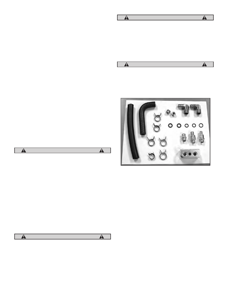
iii. Remove crankcase vent fitting (S&S PN 50-0451) and set aside
for later use. Install supplied vent fitting (S&S PN 50-0449 is for
use with 2002–’06 with 7⁄16 ID vent hose or 50-0454 is for use with
1999–’01 with 3⁄8 ID vent hose) with O-ring installed on fitting. See
Picture 1.
3
FL Oil Line Install Kit (PN 31-0425)