S&S Cycle 49-State EPA Certified Engines User Manual
Page 6
Optional S&S Two Cable Throttle Kits
Kits fit 1” (25.4mm) O.D. handlebars and can be used on most chassis. An adapter sleeve is available for use with handlebars having 7/8” (22.2mm)
ends. Fittings on provided cables readily “plug in” to S&S® Super E, G, or stock H-D 1981 and later butterfly type carburetors. Kits include one opening
side cable, one closing side cable, left and right handlebar grips, and handlebar clamps.
Throttle kit with 36” (91cm) cables PN 19-0450
Throttle kit with 39” (99cm) cables PN 19-0448
NOTE: 1981 to 1990 OEM style cables may be used as replacement cables for throttle kits above.
4- Throttle/Cables
A- Install new throttle assembly.
I- Install new throttle assembly and cables. Position grip and cables so cables can be angled towards carb for easy adjustment and free
operation.
II- Apply light coat of clean cable lubricant to cables and fittings. Loosen cable adjustment locknuts and turn adjusting screw so half of
the threads are exposed.
5- Throttle/Cable Assembly
A- Install throttle cables on carburetor.
I- Remove throttle cable housing bracket, PN 11-2339.
II- Install opening side throttle cable barrel fitting and throttle cable in throttle linkage on appropriate side of throttle cable housing
bracket. Opening side cable housing outside diameter is smaller and measures .190” (4.826mm).
III- Repeat step II for closing side throttle cable. Closing side cable has a spring around inner cable wire.
IV- Reinstall throttle cable housing bracket on carburetor.
B. Turn throttle cable adjusters to remove excessive free play. Test the throttle to ensure it opens and closes freely. The throttle should snap
shut when released. Turn handlebars to extreme left and open and close throttle, then turn bars to extreme right and repeat. If throttle
binds, loosen cable adjusters to put more free play in cables. Tighten the adjusting screw locknuts after final adjustments are made.
NOTE: Throttle grip assembly must be assembled correctly and work freely to prevent possible sticking during operation. Cable routing must be free of
tight bends to minimize cable to cable housing friction. Throttle must not bind and must snap shut to fully closed position when released.
•
•
WARNING
Incorrect cable adjustment may cause throttle to stick open, causing loss of control of motorcycle, serious injury or death.
6- Connect compression releases 4” and 41/8” bore engines only
A- The compression release wires have Deutsch connectors that are installed in-line to allow separation of the releases from the main wiring
harness.
B- Push the lead wires into the Deutsch connector until you hear a click from them as they slide into position. Verify that the wires are in place
by firmly pulling them while you hold the connector. When making these connections, there is no proper orientation to worry about—just
be sure to make solid connections. In the main wiring harness, the green wire is powered during cranking and the black is the ground.
C- Slide the orange wedge into the connector and listen for an audible click as it goes into position.
D- Connect the compression release solenoid lead wire Deutsch connectors to the main wiring harness.
E- Slide the supplied 4-foot black sleeve over the wire harness until it reaches the connectors—but keep in mind that you will have to cut the
sleeve to allow access for a fuse holder in a few steps.
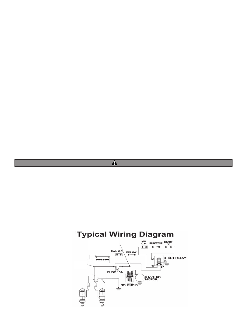
F- Use the drawing below to help locate the wiring connection points on your motorcycle.
GREEN WIRE
CONNECTION POINT
BLACK
WIRE
GREEN
WIRE
Throttle kit with 42” (107cm) cables PN 19-0482
Throttle kit with 48” (122cm) cables PN 19-0449
•
•
7/8” to 1” (22.2 to 25.4mm) Adapter sleeve PN 19-0235
•