S&S Cycle IST Ignition System for 1984-1999 Big Twin and Custom Applications User Manual
Page 6
c. After determining final position for Knock Sensor, remove mounting bolts and lockwashers, apply blue Loctite® 243 on first three threads of
bolts, then re-install. Torque mounting block to cylinder head bolt to 33 ft.-lbs., torque knock sensor to mounting block bolt to 11 ft.-lbs.
• Knock Sensor must be mounted to the rear cylinder for correct operation.
• Mounting the Knock Sensor on the front cylinder will provide an incorrect signal.
• Do not over-tighten. Torque in excess of 20 ft.-lbs. will damage the sensor.
• Hold knock sensor in position by hand only while torquing. Do NOT use pliers. Damage to knock sensor will occur.
• Do not allow knock sensor wiring to contact engine.
3. Installation of the MAP Sensor
a. Replace the existing VOES vacuum hose with the one provided. Trim the hose to a length that will locate the MAP Sensor so it does not
interfere with the engine Temperature or Knock Sensors, or motor mount hardware. A hose length in the 1 to 2 inch range is acceptable.
If the vacuum fitting in the intake manifold is used for other equipment, the line may be cut near the manifold, and the supplied tee may
be used. The total line length from the manifold to the sensor should be kept less than 9 inches - shorter if practical.
b. Remove the orange rubber seal at the end of the MAP Sensor with a pair of needle-nose pliers.
c. Attach the MAP Sensor to the hose. It is recommended to use wire ties around vacuum hose connections.
4. Ignition Coil Installation
a. A single-fire coil may be installed in the location where the wasted-spark coil was. It should have front and rear connections which go to
the module and front and rear spark plug wire connections. Other single fire coils may be used by modifying the supplied harness.
b. Do not use the motorcycle’s existing coil harness - a coil harness is provided.
c. Primary coil resistance should be in the range of 0.5 to 3 ohms.
5. Cam Position Sensor Kit Installation.
S&S® IST ignition installations for Harley-Davidson® Evolution® engines use a custom camshaft position sensor assembly that fits into the
standard nosecone style gear cover. It takes the place of the stock style ignition rotor and ignition pickup assembly.
a. Remove points cover by removing two screws. (It may be necessary to also remove two pop rivets on original factory installations).
b. Remove points cover standoff screws.
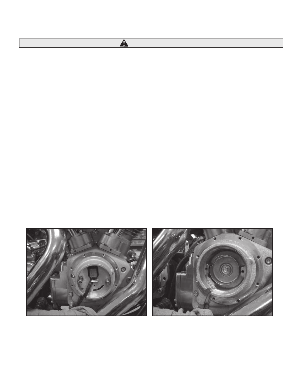
c. Remove existing ignition sensor plate and wiring from engine nosecone. See Picture 7, below left.
d. Remove existing ignition rotor. See Picture 8, below right.
NOTE: The wiring connector for the ignition needs to be removed for the wires to slip out of most nosecones. Some wiring connectors can be disassembled
for removal, others will require cutting the wires.
e. Position IST rotor on end of camshaft so that alignment pin of the sensor cup fits into alignment slot in the end of the camshaft. See
Picture 9, next page.
f. Gently rock the cup from side to side and up and down to verify the rotor pin is fully seated in the slot in the end of the camshaft.
6
CAUTION
Picture 7
Picture 8