S&S Cycle IST Ignition System for 1984-1999 Big Twin and Custom Applications User Manual
Page 4
C. Securing Motorcycle
Motorcycle must be adequately secured against falling over during the Ignition system installation! Use of tie down straps on both sides
of the motorcycle is recommended.
Disconnect negative terminal of battery to eliminate potential sparks and inadvertent engagement of the starter while working on
motorcycle.
1. Place motorcycle on a suitable repair stand so that the motorcycle is stable and secure with the rear tire elevated. Place motorcycle in 4th or
5th gear. Remove spark plugs. These steps are necessary so that the rear tire can be used to rotate the engine to place the flywheel timing
mark in the engine timing hole.
D. Removal of Existing Ignition Components
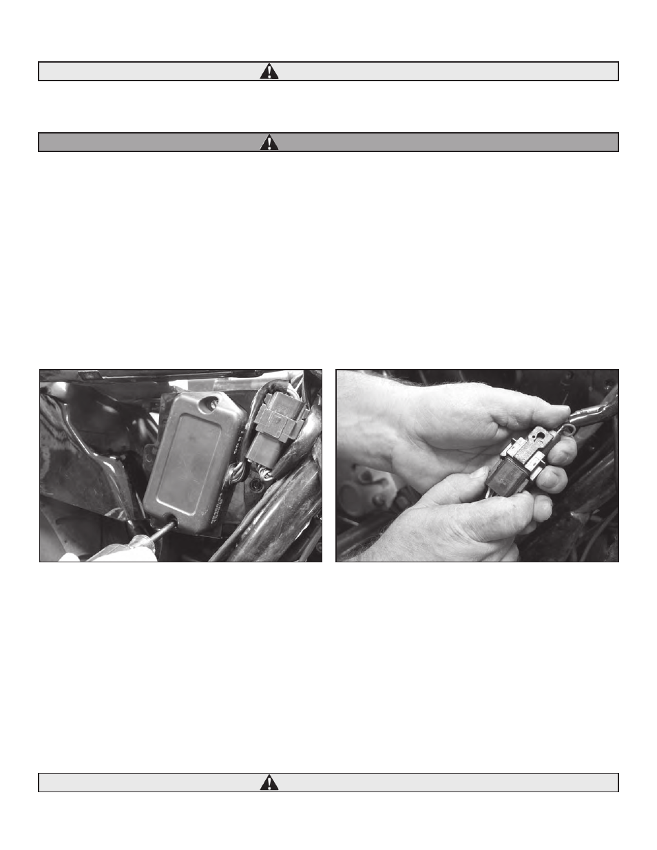
1. Ignition Module
a. Locate the ignition module installed on your motorcycle. The ignition module can usually be found under the seat, a side cover, or in front
of the engine on the frame. See Picture 3, below left. Refer to the service manual for your motorcycle if you have trouble locating it.
b. Remove the module mounting hardware and unplug the module See Picture 4, below right. The plug is disconnected by simultaneously
pressing the locking tabs on the connector and pulling the two halves away from each other. Save the mounting hardware for installation
of the S&S® ignition module.
2. Existing Coil and VOES
a. If so equipped, remove the existing dual fire ignition coil. This is usually located on the left side near the upper motor mount, above
the engine front rocker box, or to the left of the engine near the seat. Remove or insulate the “+” and module terminals in the existing
harness with heat shrink or electrical tape.
b. If so equipped, remove the existing vacuum operated electrical switch (VOES). This is located between the heads. Remove or insulate the
terminals and connector in the existing harness with heat shrink or electrical tape.
E. S&S System Installation
Although it may not be necessary in some cases, removal of the gas tank is recommended for ease of installation of the Engine Temperature
Sensor, the Knock Sensor Assembly, the Manifold Absolute Pressure (MAP) Sensor and to allow routing of the wiring harness. An alternative to
complete tank removal: Loosen (do not remove) the bolt at the front of the tank and remove the mounting bolt(s) at the rear of the tank. The
rear of the tank may then be raised slightly to allow enough room to install these components.
Clearances are limited at the front of the tank. Use care not to damage any painted surfaces while handling tank.
4
Picture 3
Picture 4
CAUTION
WARNING
CAUTION