S&S Cycle Billet Aluminum Rocker Arm Kit for X-Wedge Engines User Manual
Page 6
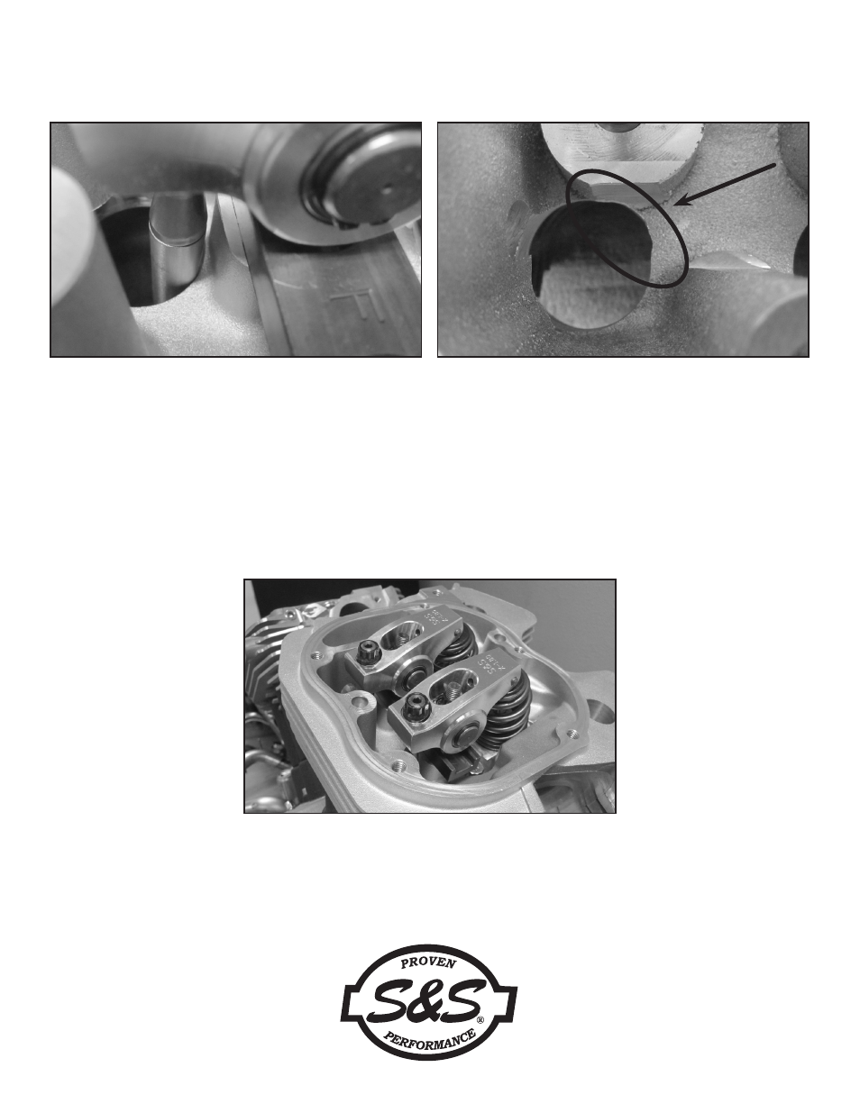
15. Confirm the clearance between the intake pushrod and the cylinder head. See Picture 11, below left. It may be necessary to remove some
material from the cylinder head to gain additional clearance. See Picture 12, below right. If this procedure is necessary, remover the rocker
arms, pedestals, alignment channel and pushrods. Place a rag down the pushrod tubes to block metal shavings and sufficiently cover the
rest of the engine.
16. Thoroughly clean the area when finished.
17. Re-install the pushrods, alignment bar, pedestals and rocker arms.
18. Apply Loctite® 262 to the 5/16", 12 point nut and install on the stud. Tighten to 30 ft-lbs.
19. Tighten the adjuster screw until the lash is removed. After this point, tight the adjuster screw an additional 2 full turns.
20. Install the 3/8" 12 point to lock the adjuster screw and torque to 26 ft-lb.
21. Allow the lifters to bleed down for 15 minutes before rotating engine.
22. Repeat procedure for rear cylinder.
Picture 11
Picture 13
Picture 12: Close up of clearance cut made for intake pushrods
- Shift Collar Replacement for S&S Transmission (7 pages)
- Secondary Drive Belt Handling and Installation (2 pages)
- X-Wedge Rubbermount (XW-R) Transmission Case with Engine and Swing Arm Mount (8 pages)
- Billet Primary Cover for 1989-06 Harley-Davidson Softail and 1991-05 Dyna Models with Forward and Mid Controls (4 pages)
- All-Helical Transmission Gear Set Cassettes for Harley-Davidson 1991-05 Dyna, 1991-06 FLT and Softail models, and Custom Applications (20 pages)
- All-Helical Transmission Complete Assembly for 1991-99 Harley-Davidson Softail and Custom Applications (8 pages)
- Speedometer Calibrator (Part 55-1007) (4 pages)
- Frame Lock (4 pages)
- Hydraulic Side Cover Kit PN 56-4060 (8 pages)
- Transmission Case, 4-to-5 Speed (8 pages)
- 5-Speed Trasmission Case for 1986-99 Big Twin and Custom Applications (4 pages)
- Rocker Arm Rebuild Kit for 1984-Up Big Twin and 1986-up Harley-Davidson Sportster Models (4 pages)
- Rocker Boxes for 1966-84 Big Twin (7 pages)
- Billet Rocker Cover Assemblies for Harley-Davidson evolution engines (8 pages)
- Billet Rocker Covers for Harley-Davidson Twin Cam 88 (4 pages)
- Die-Cast Rocker Covers for 1984–99 and 1999–14 Harley-Davidson Big Twin Engines and S&S V-Series and T-Series engines (7 pages)
- Quickee Pushrod Supplement (1 page)
- Rocker Arm Rebuild Kit for 1966-1984 Big Twin Engines (4 pages)
- Cams for Panhead, Shovelhead, & Harley-Davidson Evolution Engines (8 pages)
- Chain Drive Camshaft Set for Harley-Davidson Twin Cam 88 Engines (8 pages)
- Gear Drive Cams for Harley-Davidson Twin Cam 88 Engines (8 pages)
- Hydraulic Lifter Limited Travel Kit Fits All Harley-Davidson Evolution Engines (2 pages)
- Pushrod Kits and Travel Limiters (all) (8 pages)
- Pushrod Kit for Harley-Davidson Twin Cam 88 Engines (1 page)
- Valve Spring Kits for 1984-2004 Big Twin & 1986-2003 Four-Cam (90-2077 and 90-2078) (4 pages)
- 590 Lift Valve Spring Kits 90-2060 and 90-2063 for 1948–1984 Big Twin Engines (4 pages)
- Spring Kit 90-2053 (Fits all Panhead and Shovelhead Engines) (2 pages)
- High Performance Valve Spring Kits 90-2079, 90-2080 and 90-2081 (4 pages)
- Hydraulic Tappet PN 33-5342 (2 pages)
- Valve-To-Valve Clearances in S&S Shovel-Style Cylinder Heads (1 page)
- Sidewinder Valve Spring Kits for 1984-04 Big Twin and 1986-03 Four-Cam Engines (PN 90-2069) (4 pages)
- OHV BT and KN-Series 1936-47 Flathead Power Rocker Arms and Rocker Shafts (8 pages)
- 2006-Up Gear Drive Cams for Harley-Davidson Twin Cam 88 Engines (12 pages)
- Chain Drive Camshaft for 2007-Up Big Twin and 2006-Up Harley-Davidson Dyna (7 pages)
- Standard and Easy Start Chain Drive Camshafts for Harley-Davidson Twin Cam 88 Engines 1999–2006 Big Twin, except 2006 Dyna models (8 pages)
- Standard and Easy Start Chain Drive Camshafts for 2006 Harley-Davidson Dyna models and all 2007-up Big Twins (8 pages)
- Standard & Easy Start Gear Drive Camshafts for 2007–up Harley-Davidson Big Twin and 2006 Dyna Models (8 pages)
- Adjustable Pushrods (4 pages)
- Spring Kits on 7mm Valve Stems (1 page)
- 650 Lift Conical Valve Spring Kits for 1984–Up Big Twin and 1986–Up Four-Cam Engines (PN 106-5909 & 900-0050) (4 pages)
- Easy Start Camshafts for X-Wedge Engines (12 pages)
- Pushrod Kits 1936-84 BT & 1957-85 XL (5 pages)
- 585 Sidewinder Valve Spring Kits for X-Wedge Engines (3 pages)
- Flathead Power Rocker Cover Gaskets (1948–65) P/N 900-0339 (Set) 900-0329 (Individual) (1 page)