Caution – S&S Cycle Gear Drive Cams for Harley-Davidson Twin Cam 88 Engines User Manual
Page 6
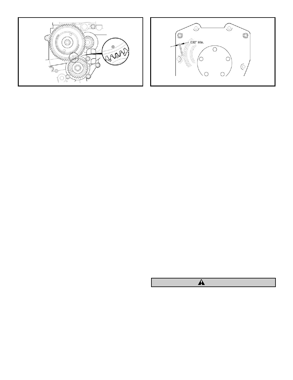
Figure 5
Figure 4
I.
Install oil pump mounting bolts with a drop of Loctite
®
threadlock 242 or 243 (blue) according to procedure
found in factory service manual: Gently bottom screws,
then back them out
1
⁄
4
turn. Center oil pump by rotating
engine by hand while snugging down screws.
Alternately tighten bolts to 95 in-lbs. torque in
sequence shown. See Figure 1. Before moving
forward, verify that inner drive gears rotate freely
and no binding is present.
NOTE: Crankshaft and cam drive gears have a light press fit on
their respective shafts. Start gears squarely on their shafts and use
their mounting bolts to pull them all the way into position.
NOTE: Make sure that no metal burrs are raised when installing
the gear sets. Burrs can form underneath the gear causing
excessive gear run out.
Checking the inner cam gear and outer drive gear sets for
backlash:
It is important to check the inner 31 teeth gear set and the
outer drive gear set (pinion 31 teeth gear and cam drive 62
teeth gear) for the correct backlash before installing the rest of
the valve train components. Backlash, the measure of free play
between the gear set, must be checked with no loading applied
to the cams and in the four different camshaft positions. To
check the backlash of the inner cam gears, lock the front cam
into a position by applying a force to the cam lobe. Measure the
backlash by moving the rear cam set back and forth. To check
backlash in the outer drive gear set, rotate the 62 teeth cam
drive gear back and forth while keeping the pinion gear locked
in one place with the engine. The minimal required backlash for
the gear sets should be between .0005” and .001”and no more
than .002” for cold gears. The both gear sets should roll freely
with no radial or axial binding. If when checking backlash the
gear mesh shows less than .0005” of backlash then a smaller
crankshaft gear size 33-4160X for the outer gears or 33-4272RX
for the inner gears should be used. Gear sets with less than
.0005” of backlash may whine when run and can cause tooth
wear excessive heat generation and gear failure resulting in
engine damage. Gear backlash greater than .002” can cause
excessive gear noise or clicking caused by the reversing of the
forces applied by the lifter springs onto the gears, use the
oversized crankshaft gear 33-4160Z for the outer gears and
33-4272RZ for the inner gears to correct this condition.
J.
Place crankshaft gear on crankshaft with timing mark
outward. Apply a drop of red Loctite
®
threadlock 262,
271 or 272 to threads of
5
⁄
16
"-18 x
3
⁄
4
" Grade 8 crankshaft
gear bolt, provided in S&S
®
Camshaft Kit 33-5163 or
obtained from another source. Apply a drop of clean
20W-50 engine oil under bolt flange. Using the washer
removed in disassembly step G, install crankshaft gear
bolt and tighten to 25 ft-lbs. torque.
K.
If necessary, place transmission in high gear and turn
rear wheel to rotate engine until timing mark on
crankshaft gear is in position. See Figure 4.
L.
Place drive gear key in rear camshaft. Position cam drive
gear on rear camshaft and key with timing mark outward.
Rotate drive gear and camshafts until drive gear and
crankshaft gear timing marks are aligned. See Figure 4.
M. Apply a drop of red Loctite
®
threadlock 262, 271 or 272
to threads of
3
⁄
8
"-24 x 1.75 Grade 8 cam drive gear bolt.
Apply a drop of clean 20W-50 engine oil under bolt
flange. Using thick washer provided, install cam drive
gear bolt and tighten to 34 ft-lbs. torque. Verify that out
gear drives rotate freely and no binding is present.
NOTE: Drive gear cams are slightly larger than stock drive
sprocket and needs to be checked for interference with cam
cover before proceeding.
N.
Press a small piece of clay or kneadable putty on cam
cover mounting boss shown. See Figure 5. Carefully hold
cover and cover gasket in position against crankcase.
Install mounting bolts (4) near corners of cover finger
tight. Push or tap cam cover towards front of engine.
O.
Carefully remove cam cover. Determine cover-to-gear
clearance by measuring impression left in clay by gear at
its thinnest point. Clearance should be .030" or more.
If clearance is less than .030", or if cover contacts gear,
remove only enough material from cam cover to obtain
correct clearance. Repeat steps M and N if necessary.
Be careful not to grind too deeply and break through to the
outside of the cam cover. Damage to cam cover caused by
removing too much material is not covered under warranty.
P.
Use a new gasket and install cam cover. Tighten
cover bolts to 90-120 in-lbs. torque in sequence
shown. See Figure 6.
Q. Remove clips to release lifters. If necessary, place
transmission in high gear and turn rear wheel to rotate
engine until both lifters for front cylinder are at lowest
point on camshaft (TDC of compression stroke for
front piston).
6
CAUTION