Caution – S&S Cycle Gear Drive Cams for Harley-Davidson Twin Cam 88 Engines User Manual
Page 4
I.
Working gradually around edge of each sprocket,
carefully pry sprockets loose. Remove sprocket and
chain assembly.
J.
Remove chain guide. See Picture 4.
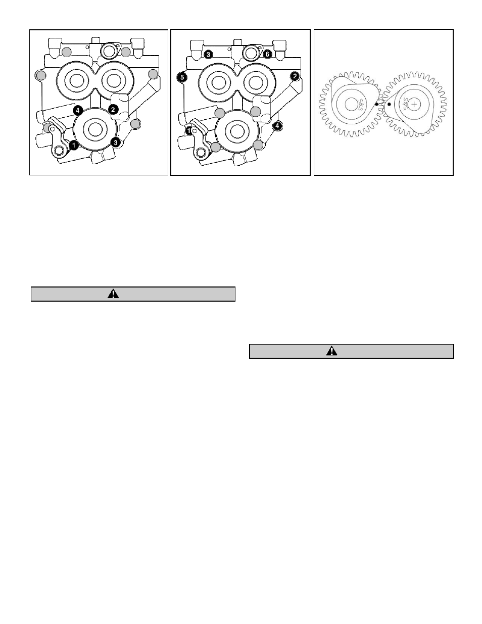
K.
Following sequence shown, alternately loosen and
remove oil pump bolts. See Figure 1.
L.
Following sequence shown, alternately loosen and
remove cam support plate bolts. See Figure 2.
Failure to remove and install bolts according to correct procedure
may result in parts damage not covered under warranty.
M. Carefully remove cam support plate assembly from case.
All references to Harley-Davidson
®
part numbers is for
identification purposes only. We in no way are implying that
any of S&S
®
Cycle’s products are original equipment parts or
that they are equivalent to the corresponding Harley-
Davidson
®
part number shown.
NOTE: It is not necessary to remove oil pump from engine to
complete this installation unless grinding in gear case must be
performed for clearancing. If grinding is to be done all gear case
components must be removed and all holes taped off with duct
tape to avoid contamination of engine with chips.
N.
Use Harley-Davidson
®
cam chain tensioner unloader
H-D
®
#42313 to move tensioner away from secondary
cam chain. Secure tensioner by inserting second
retention pin through front of support plate.
O.
Remove bearing retainer screws and bearing retainer
from cam support plate.
P.
With cam support plate positioned securely in a
hydraulic press, use Harley-Davidson
®
camshaft
remover/installer H-D
®
#43644 to press both camshafts
and bearings from support plate simultaneously.
NOTES:
G Cam bearings may have a loose fit in cam support plate.
Camshaft and bearing assemblies may drop out when
beginning pressing procedure. Camshafts with roller style
bearings will be loose and drop out of support plate.
G The S&S Gear Drive Cams require that ball bearings be used
for both front and rear camshaft outer bearings. The roller
bearing used for the rear camshaft in some stock engines has
too much internal clearance. This allows center to center
distance of gears to vary, causing excessive gear noise. Since
the gear drive does not exert a large side load on the rear
camshaft, the higher load handling capacity of the roller
style bearing is not required.
Q. Use Harley-Davidson
®
cam chain tensioner unloader H-D
®
#42313 to remove retention pin from either tensioner.
Allow tensioner to completely relax. Remove retaining
ring and tensioner assembly from cam support plate.
Repeat this procedure for remaining tensioner.
2.
Install Gear Drive Cams
Check pinion shaft runout. Indicate end of pinion shaft at cam
support plate bushing surface and rotate engine; reading must
be .003” or less total indicated reading (TIR). If reading is greater
than .003” TIR the crankshaft must be repaired or replaced to
correct excess runout before installing gear drive cams. Failure to
correct excess runout may lead to engine damage not covered
under S&S warranty.
NOTE: Do not reuse cam bearings. If S&S Camshaft Installation Kit
33-5163 is not being used, new bearings should be obtained from
another source and installed with new camshafts. The S&S Gear
Drive Cams require that ball bearings be used for both front and
rear camshaft outer bearings.
A.
Apply assembly lube to outer races of cam bearings and
bearing bores in support plate. With cam support plate
positioned securely in a hydraulic press, use Harley-
Davidson
®
camshaft remover/installer H-D
®
#43644 to
install both bearings. See Picture 5.
NOTE: Check clearance between bearing retainer and woodruff
keys securing inner gears to cams. Remove material from
retainer, to provide .030" clearance between key and retainer.
See Picture 6.
B.
Align hole in bearing retainer with oil passage in
support plate. Install bearing retainer screws with a
drop of blue Loctite
®
threadlock 242 or 243 and
tighten screws to 20-30 in-lbs. torque.
4
Figure 1
Figure 2
Figure 3
CAUTION
CAUTION