Caution – S&S Cycle Gear Drive Cams for Harley-Davidson Twin Cam 88 Engines User Manual
Page 5
C.
Apply assembly lube to outer bearing surface of front
(shorter) camshaft and inner race of front bearing.
Support bearing by inner race and press camshaft all
the way into bearing. Install retaining ring on outer
end of front camshaft.
NOTE: Do not reuse retaining ring. If S&S Camshaft Installation
Kit 33-5163 is not being used, a new retaining ring be obtained
from another source and installed with new camshaft.
D.
Apply assembly lube to outer bearing surface of rear
(longer) camshaft and inner race of rear bearing.
Support bearing by inner race and with camshaft gear
timing marks aligned (See Figure 3), press camshaft all
the way into bearing.
All references to Harley-Davidson
®
part numbers is for
identification purposes only. We in no way are implying that any
of S&S
®
Cycle’s products are original equipment parts or that they
are equivalent to the corresponding H-D
®
part number shown.
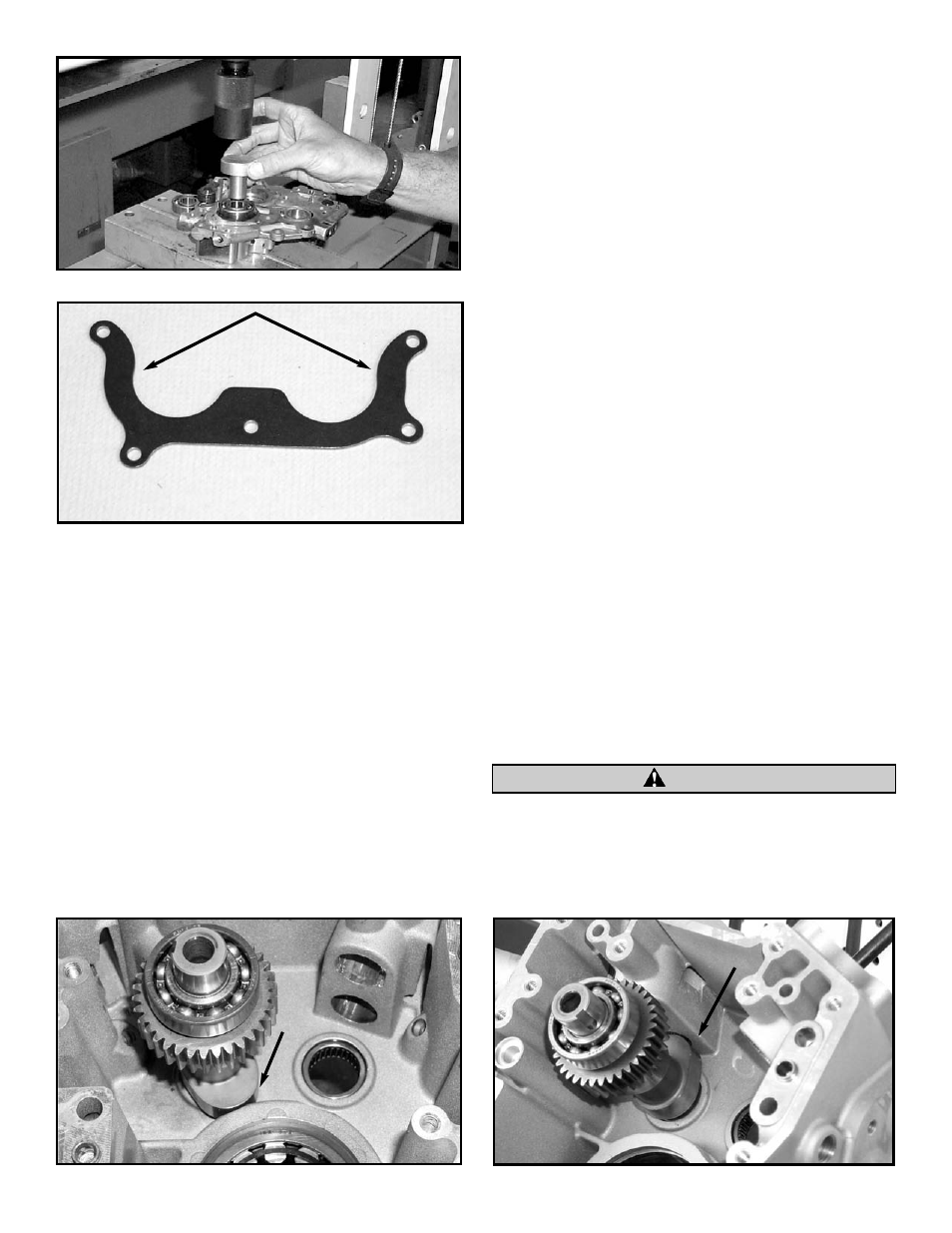
E.
When using 585G, 625G, or 640G camshafts (33-5168,
33-5170, or 33-5172) clearance between pinion bearing
boss and rear cam lobe must be checked. See Pictures
7 & 8. Remove just enough material to provide .030"
clearance between top of cam lobe and pinion bearing
boss when camshaft is rotated in inner needle bearing.
Also check clearance between all cam lobes and tappet
guide bosses. To avoid contamination of engine with
chips, we recommend that all holes in the gear case be
taped off with duct tape and that gear case be
thoroughly cleaned with parts cleaner or solvent after
clearancing is performed.
F.
Carefully remove camshaft needle bearings from
crankcase with Harley-Davidson
®
camshaft needle
bearing remover/installer H-D
®
#42325, and replace
them with new bearings provided in S&S Camshaft
Installation Kit 33-5163, or with bearings from
another source. Cam bearings must be Torrington
B148 full complement bearing or equivalent.
NOTE: Before reinstalling cam support plate, make sure oil
pump O-rings are in good condition and remain in place
during following procedure. Replace worn or damaged O-rings
if necessary.
G.
Apply a thin layer of assembly lube to cam journals, lobe
surfaces, and inner bearing surfaces. Align camshafts
with needle bearings and carefully slide support plate
over crankcase dowels.
NOTE: Support plate assembly should slide into place without
resistance. If resistance is encountered, determine cause and
correct problem before proceeding. Do not force support
plate into position!
H.
Loosely install support plate screws with a drop of
Loctite
®
threadlock 242 or 243 (blue). Alternately
tighten screws to 95 in-lbs. torque following sequence
shown. See Figure 2.
Support plate screws that pass through alignment dowels (See
positions 1 & 2 in Figure 2) can be easily stripped when
applying maximum 120 in-lbs. torque as recommended by
Harley-Davidson
®
.
5
Picture 5
Picture 6
Picture 7
Picture 8
If additional clearance is required, remove
material from areas indicated to provide
.030" clearance between key and retainer.
CAUTION