Recommended modbus wiring, Termination jumper, Modbus master m2 – RKI Instruments M2 Rig Monitor User Manual
Page 40: 35 m2 rig monitor operator’s manual, Termination jumper installed, Termination jumper not installed
35
M2 Rig Monitor Operator’s Manual
Recommended Modbus Wiring
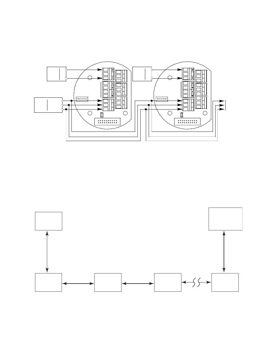
The recommended Modbus wiring for the Rig Monitor is illustrated in Figure 12 below. In
this configuration, 5 wires are used for wiring the Rig Monitor into a Modbus system.
Figure 12 also illustrates typical alarm device wiring.
Figure 12: Recommended Modbus Wiring
Termination Jumper
The Rig Monitor includes a 2-pin termination header (see Figure 4) that is used when the
Rig Monitor is used in a Modbus system. Every Rig Monitor is supplied with a
termination jumper (a jumper block) installed onto this header. If the Rig Monitor is not
used in a Modbus system, this jumper has no function. When the Rig Monitor is installed
in a Modbus system, this jumper must be installed in an Rig Monitor that is at the end of a
Modbus line. Any Rig Monitor in a Modbus system that is not at the end of a line must
have the termination jumper removed (see Figure 13 & Figure 14 below).
Figure 13: Multiple M2 Rig Monitors in a Daisy Chain Configuration
C
N
C
NO
-
24 VDC
Factory
Wired
+
S
PW
R
/S
IG
FA
IL
PW
R
/S
IG
S
C
N
C
NO
FA
IL
To
Additional
M2s
Power
Converter
AL
A
R
M
2
A
B
C
RS
4
8
5
RS
4
8
5
A
B
C
AL
A
R
M
2
Input
Terminals
D1
D0
Power
Converter
Factory
Wired
24 V DC
-
+
Modbus
Controller
Common
C
N
C
NO
C
N
C
NO
TO
X
IC
O
X
Y
C
N
C
NO
AL
A
R
M
1
See
Detector
Wiring
See
Detector
Wiring
AL
A
R
M
1
C
N
C
NO
TO
X
IC
O
X
Y
Modbus
Master
M2
Termination
Jumper
Installed
M2
Termination
Jumper
Not Installed
M2
Termination
Jumper
Not Installed
M2
Termination
Jumper
Not Installed
M2
Termination
Jumper
Not Installed
ID = 128
ID = 127
ID = 126
ID = 125
ID = 1
Up to 128 M2s can be connected without a repeater.
RS-485
RS-485