Connecting dc power, Connecting external alarms, Figure 9: rig monitor field wiring – RKI Instruments M2 Rig Monitor User Manual
Page 18: 13 m2 rig monitor operator’s manual
13
M2 Rig Monitor Operator’s Manual
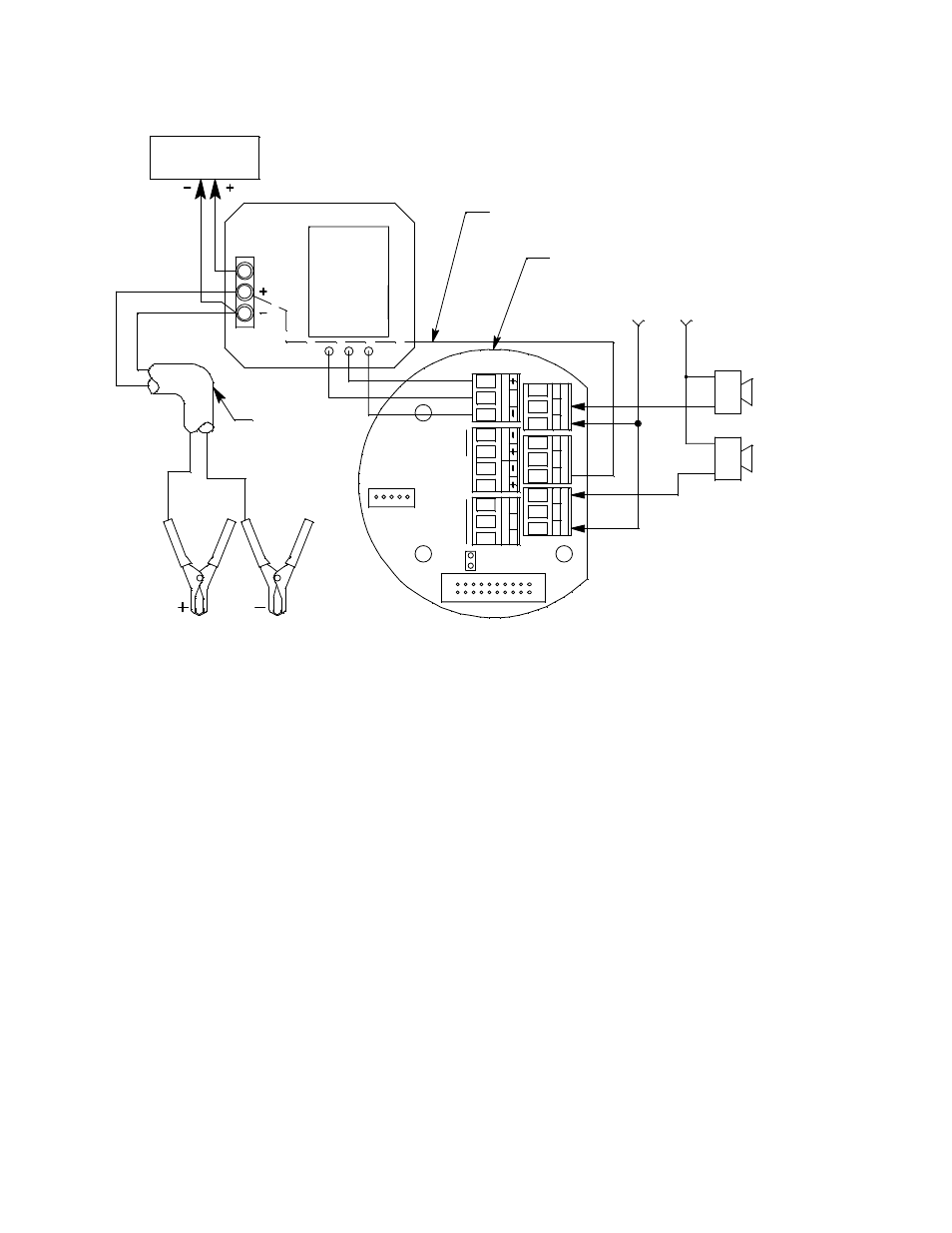
Figure 9: Rig Monitor Field Wiring
Connecting DC Power
Perform the following functions to connect the Rig Monitor to DC power. One end of the
battery cable is already factory wired to the appropriate terminals at the Rig Monitor
housing. Use the other end to connect a 12 VDC battery.
1.
Connect the red battery clamp to the (+) terminal of the 12 VDC battery.
2.
Connect the black battery clamp to the (-) terminal of the 12 VDC battery.
Connecting External Alarms
Perform the following procedure to connect external alarms to the Rig Monitor’s Fail or
Alarm 2 terminals. The Alarm 1 terminals are factory wired and are not available for field
use.
1.
Disconnect the battery clamps from the + and - terminals of the 12 VDC battery.
2.
Remove the junction box cover.
3.
Grasp the control PCB by its edges.
4.
Gently pull until the control PCB is pulled away from the banana jacks. Take care not
to pull too hard and damage the cable which connects the control and terminal PCB’s.
5.
Let the control PCB hang by the cable. The terminal strips are now visible on the
terminal PCB. The control PCB may be left hanging while wiring is done.
6.
Locate the relay terminal strips. See Figure 4 to assist you in locating the relay
terminal strips.
Alarm Device Power
Term inal PCB
Factory W ired (Shown f or Reference)
AL
AR
M
2
C
NC
NO
R
S
485
Typical Alarm
W iring Shown
A
B
C
TO
X
IC
O
X
Y
AL
A
R
M
1
Alarm 2
Device
C
NC
NO
Black
White
Power Converter
4 - 20 mA
Recording Device
4-20 mA
out (S)
Black
White
(Factory W ired
shown f or Reference)
Black
Red
S
PW
R
/S
IG
Not
Used
Red (Factory Wired)
Blue (Factory Wired)
Black (Factory W ired)
See
Modbus
Wiring
Battery Cable
Fail Alarm
Device
FA
IL
C
N
C
N
O