Internal description, Power converter, Terminal pcb – RKI Instruments M2 Rig Monitor User Manual
Page 11: Power/signal terminal strip sensor terminal strip, M2 rig monitor operator’s manual 6
M2 Rig Monitor Operator’s Manual
6
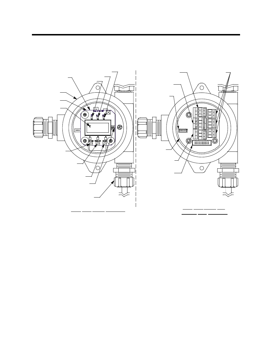
Internal Description
This section describes the internal components of the M2 Rig Monitor. The internal
components of the Rig Monitor include the terminal PCB which provides for all the
wiring connections to the Rig Monitor and the control PCB which displays the gas reading
and has the control buttons.
Figure 4: M2 Rig Monitor Internal Components
Power Converter
The power converter is located below the control PCB and is connected with standoffs
that are permanently attached to the control PCB. The power converter takes 12 VDC
voltage supplied to the Rig Monitor and converts it to 24 VDC which is used to run the
Rig Monitor. The power converter includes a three point terminal strip for field
connection of the 12 VDC supply and a recording device, gas-monitor controller, or
programmable controller. The terminal strip is accessible when the control PCB is pulled
away as described in “Wiring the M2 Rig Monitor” on page 12.
Terminal PCB
The terminal PCB is encapsulated in epoxy for protection against moisture and physical
damage. It is mounted into the rear of the junction box with three standoffs and rests on a
thin layer of foam. A banana jack is screwed into each of the standoffs and used for
mounting the control PCB. The terminal PCB converts the electrical output from the
detector to a signal which can be displayed by the LCD display, a 4 - 20 mA signal (that
corresponds to the detection range), and an RS-485 Modbus output signal. The 4 - 20 mA
Relay
Terminal Strips
PW
R
/SI
G
OX
Y
OX
Y
TO
X
IC
PW
R
/SI
G
TO
X
IC
-
S
+
-
S
+
C
NC
NO
C
N
C
N
O
C
NC
NO
Power/Signal
Terminal Strip
Sensor
Terminal Strip
AL
A
R
M
2
A
L
A
R
M
1
FA
IL
Modbus
Terminal Strip
LCD Display
Power Converter
(Under Control
PCB)
Junction Box
RKI INSTRUMENTS
M2 TRANSMITTER
Control PCB
Ribbon Cable
Connector
Down/No
Control Switch
Up/Yes
Control Switch
Contrast
Potentiometer
Enter Control Switch
Cable Bushing (3X)
Fail LED
Alarm 1 LED
Alarm 2 LED
A
B
C
RS
4
8
5
RS
4
8
5
A
B
C
View With Cover and
Control PCB Removed
View With Cover Removed
Programming
Connector
(FACTORY
USE ONLY)
Terminal PCB