Alternate modbus wiring for existing installations, Figure 27: recommended modbus wiring, 51 m2 transmitter operator’s manual – RKI Instruments M2 Series User Manual
Page 56: Power supply, Modbus controller
51
M2 Transmitter Operator’s Manual
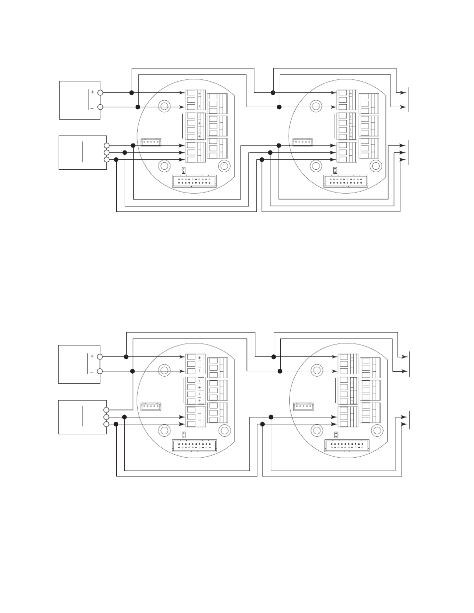
Figure 27: Recommended Modbus Wiring
Alternate Modbus Wiring For Existing Installations
Although the wiring shown in Figure 27 is recommended, it is possible to wire the M2
into a Modbus system with only 4 wires in situations where a pre-existing system is being
replaced and wiring is already in place. This should only be done if wiring for a system
that is being replaced is already installed and it is not practical to run another wire. See
Figure 28 below for this wiring configuration. In this configuration, the wire between the
“C” terminal on the M2 and the Common terminal on the Modbus controller is omitted.
Instead, the Common terminal on the Modbus controller is connected to the “-” of the 24
VDC power supply.
Figure 28: Alternate Modbus Wiring
C NC NO
C NC NO
C NC NO
ALARM 2
ALARM 1
F
AIL
A B C
RS 485
PWR/SIG
S
T
O
XIC O
X
Y
See
Detector
Wiring
24 VDC
Power Supply
D
Modbus
Controller
0
D
1
Input
Terminals
Common
C NC NO
C NC NO
C NC NO
ALARM 2
ALARM 1
F
AIL
A B C
RS 485
PWR/SIG
S
T
O
XIC O
X
Y
See
Detector
Wiring
To
Additional
M2s
C NC NO
C NC NO
C NC NO
ALARM 2
ALARM 1
F
AIL
A B C
RS 485
PWR/SIG
S
T
O
XIC O
X
Y
See
Detector
Wiring
24 VDC
Power Supply
D
Modbus
Controller
0
D
1
Input
Terminals
Common
C NC NO
C NC NO
C NC NO
ALARM 2
ALARM 1
F
AIL
A B C
RS 485
PWR/SIG
S
T
O
XIC O
X
Y
See
Detector
Wiring
To
Additional
M2s