Internal description, Terminal pcb, View with cover and control pcb removed – RKI Instruments M2 Series User Manual
Page 15: View with cover removed, M2 transmitter operator’s manual 10, Up/yes, Dow n/no enter modbus terminal s trip, Magnetic switc hes junction b ox
M2 Transmitter Operator’s Manual
10
Internal Description
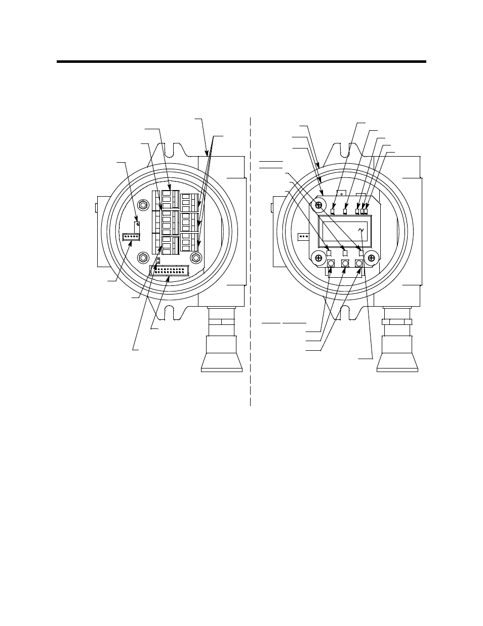
This section describes the internal components of the M2. The internal components of the
M2 include the terminal PCB which provides for all the wiring connections to the M2 and
the control PCB which displays the gas reading and has the control buttons.
Figure 9: M2 Internal Components
Terminal PCB
The terminal PCB is encapsulated in epoxy for protection against moisture and physical
damage. It is mounted into the rear of the junction box with three standoffs and rests on a
thin layer of foam. A banana jack is screwed into each of the standoffs and used for
mounting the control PCB. The terminal PCB converts the electrical output from the
detector to a signal which can be displayed by the LCD display, a 4 - 20 mA signal (that is
proportional to the detection range), and an RS-485 Modbus output signal. The 4 - 20 mA
signal may be used by a recording device, gas monitor controller, or programmable
controller. The Modbus output may be used to connect the M2 to a Modbus network. The
terminal PCB also controls three relays, one fail and two gas alarm relays.
Two columns of plug-in style terminal strips are used to make all wiring connections to
the M2. The column on the left consists of the power/signal, detector, and Modbus
terminal strips. The column on the right consists of the relay terminal strips. A 20 position
UP/YES
C
NC
NO
PW
R
/SI
G
AL
A
R
M
1
FA
IL
-
S
+
LE
L
-
S
+
PW
R
/SI
G
RS
4
8
5
AL
AR
M
2
A
B
C
RS
4
8
5
A
B
C
DOW N/NO
ENTER
Modbus
Terminal S trip
C
N
C
N
O
R KI IN STRU M EN TS
M 2 T RANSM IT TE R
LE
L
C
NC
N
O
R
W
G
B
R
W
G
B
LCD D isplay
Push B utton
Control S witches
ENTER
DOWN/NO
UP/YES
Terminal P CB
Control P CB
TX LED
RX LE D
Alarm 2 L ED
Alarm 1 L ED
Fail LED
View With Cover and
Control PCB Removed
Magnetic
Switc hes
Junction B ox
View With Cover Removed
Detector Current Pot
(Com b/CO 2 T ype
O nly, F ac tory A djust)
Display Ribbon
Cable C onnector
Termination J umper
Program ming
Connector
(Factory Use)
Detector Term inal S trip
(Com b/CO2 V ersion S hown)
Power/S ignal
Terminal S trip
3/4" NPT C onduit O pening
for W ire E ntry
Relay
Terminal
Strips