Wiring the m2 transmitter, Detector wiring, M2 transmitter operator’s manual 18 – RKI Instruments M2 Series User Manual
Page 23: Black green white red
M2 Transmitter Operator’s Manual
18
Wiring the M2 Transmitter
WARNING:
Always verify that the power source is OFF before making any wiring
connections.
1.
Remove the junction box cover.
2.
Grasp the control PCB by its edges.
3.
Gently pull until the control PCB is pulled away from the banana jacks. Take care not
to pull too hard and damage the cable which connects the control and terminal PCB’s.
4.
Let the control PCB hang by the cable. The terminal strips are now visible on the
terminal PCB. The control PCB may be left hanging while wiring is done. If desired,
the control PCB may be disconnected from the cable and set aside while wiring.
5.
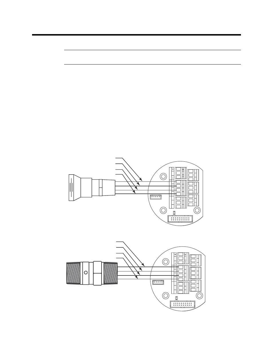
The detector leads are factory wired. Verify that the detector leads are wired to the
detector terminal strip as shown in the applicable figure below:
•
Catalytic LEL/Combustible IR/CO
2
Detectors
The wiring for these types of detectors is the same. Red wire to terminal labeled
LEL R, white wire to terminal labeled LEL W, green wire to terminal labeled LEL
G, black wire to terminal labeled LEL B.
Figure 17: Catalytic LEL Detector Wiring
Figure 18: Combustible IR/CO
2
Detector Wiring
C NC NO
C NC NO
C NC NO
ALARM 2
ALARM 1
F
AIL
A
B C
RS 485
PWR/SIG
LEL
S
R W G B
Black
Green
White
Red
A
B C
RS 485
PWR/SIG
LEL
S
R W G B
C NC NO
C NC NO
C NC NO
ALARM 2
ALARM 1
F
AIL
A B C
RS 485
PWR/SIG
LEL
S
R
W G B
Black
Green
White
Red
A B C
RS 485
PWR/SIG
LEL
S
R
W G B