Installation, 2496rk, 2499rk – RKI Instruments 65-2499RK User Manual
Page 8: Mounting the co detector
4 • 65-2496RK/65-2499RK CO Detector
Installation
This section describes procedures to mount the CO detector in the monitoring
environment and wire the detector to a controller.
Mounting the CO Detector
NOTE: If you are installing a 65-2496RK, it does not include a junction box and is usually
factory installed in one of a controller’s conduit hubs or may be field installed
using the 3/4” NPT threads on the end with the wires. The 65-2499RK includes a
junction box as shown in Figure 3 below.
1.
Select a mounting site that is representative of the monitoring environment. Consider
the following when you select the mounting site.
•
Select a site where the detector is not likely to be bumped or disturbed. Make sure
there is sufficient room to perform start-up, maintenance, and calibration
procedures.
•
Select a site where the target gas is likely to be found first.
NOTE:
If your application does not require a specific mounting site, mount the detector
at approximately breathing level.
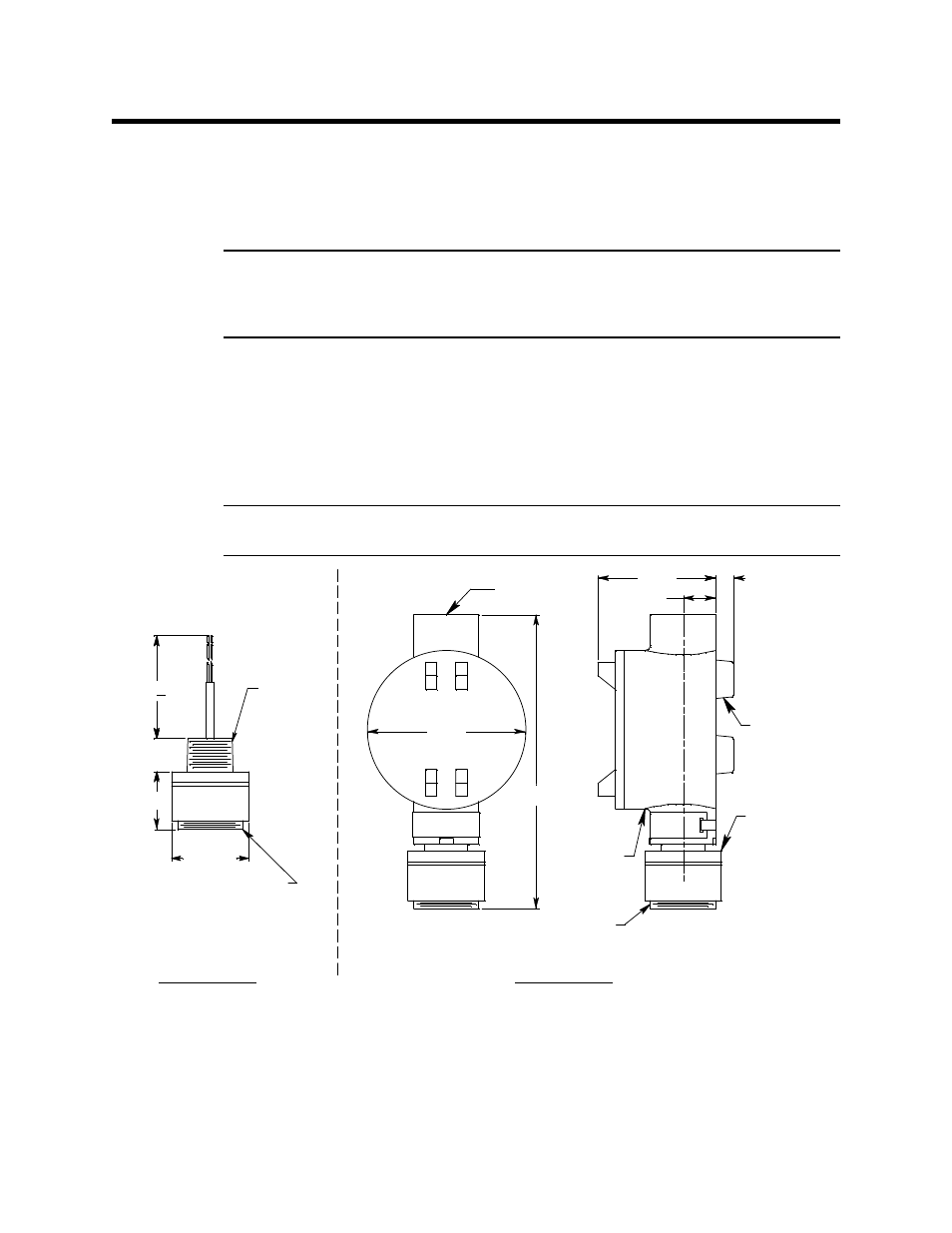
Figure 3: Outline & Mounting Dimensions, 65-2496RK & 65-2499RK
2.
At the mounting site you select, hang or mount the junction box with the detector
facing down (see Figure 3).
CO
Detector
Rubber
Spacer, 3X
.38
.75
2.70
7.30 .25
3.65
3/4" NPT
+
Ø 1.75
1 1/2-20 Thread for
Calibration Cup
65-2496RK
3/4 NPT
Conduit Hub
65-2499RK
1 1/2-20 Thread for
Calibration Cup
Junction
Box
6.80 Max
1.32
.75