Description, Co detector – RKI Instruments 65-2432RK-05 User Manual
Page 6
2 • 65-2432RK-05 CO Transmitter
Description
This section describes the components of the CO transmitter. The transmitter consists of
the CO detector, amplifier, and junction box.
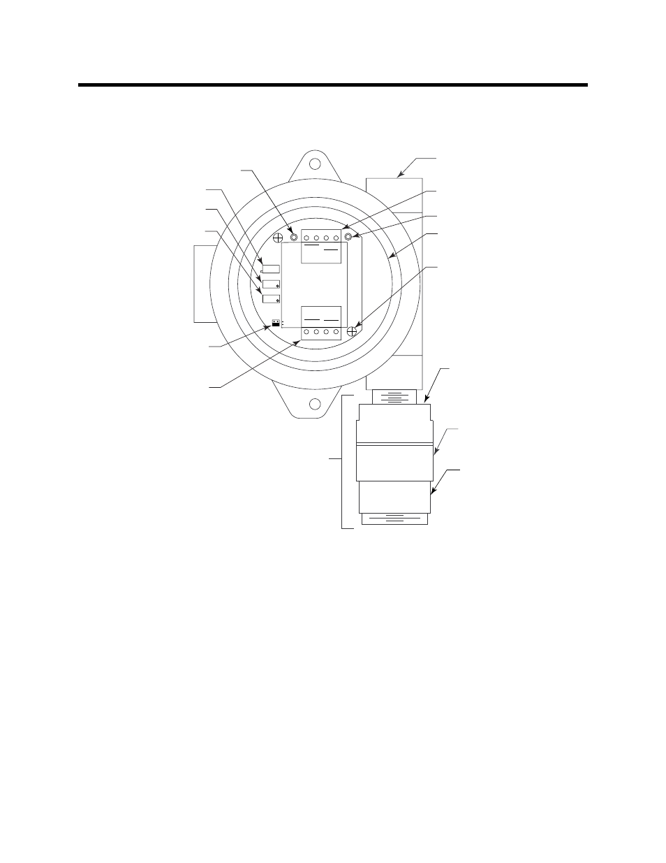
Figure 1: CO Transmitter Component Location
CO Detector
The CO detector includes the detector housing and sensor.
Detector Housing
The detector housing protects the sensing components within the housing. Use the
mounting threads at the top of the housing to screw the CO detector into the bottom
conduit hub of the junction box. Use the removable cap near the bottom of the housing to
access the sensor for maintenance or replacement. The cap protects the sensor from
damage and includes a flame arrestor which contains any sparks which may occur within
the detector housing. A cap gasket seals the interface between the housing and cap. A
flame arrestor guard is permanently bonded to the cap.
Two wires extend from the top of the detector housing. Use these wires to connect the CO
detector to the amplifier. The housing includes a four-socket pattern. This socket pattern
accepts the sensor’s four pins to secure the sensor within the detector housing. A pre-
amplifier, located between the sockets and two interconnect wires, conditions the sensor’s
signal before the signal reaches the amplifier.
3/4" NPT Conduit Opening
For Wire Entry
TOXIC
ZERO
SPAN
Not
Used
4/20
FB
+
24V
POWER/SIG
OXY
W
G
SENSOR
TP
-
TP
+
TOXIC
RD
BK
OXYGEN
Interconnect Terminal
Strip
Test Point (+)
Amplifier
Securing Screw (2X)
Detector
Housing
Detector Housing
Cap
Flame Arrestor
Guard
Carbon Monoxide
Detector
Test Point (-)
Factory Set
Potentiometer
Zero
Potentiometer
Span
Potentiometer
Jumper Block
Installed On Toxic
Select Header
Detector Terminal
Strip