Description, S sensor, Sealing spacer – RKI Instruments 65-2424RK User Manual
Page 6: Amplifier pcb
2 • 65-2424RK H
2
S Transmitter
Description
This section describes the components of the H
2
S transmitter. The transmitter consists of
the H
2
S sensor, sealing spacer, amplifier printed circuit board (PCB), and enclosure.
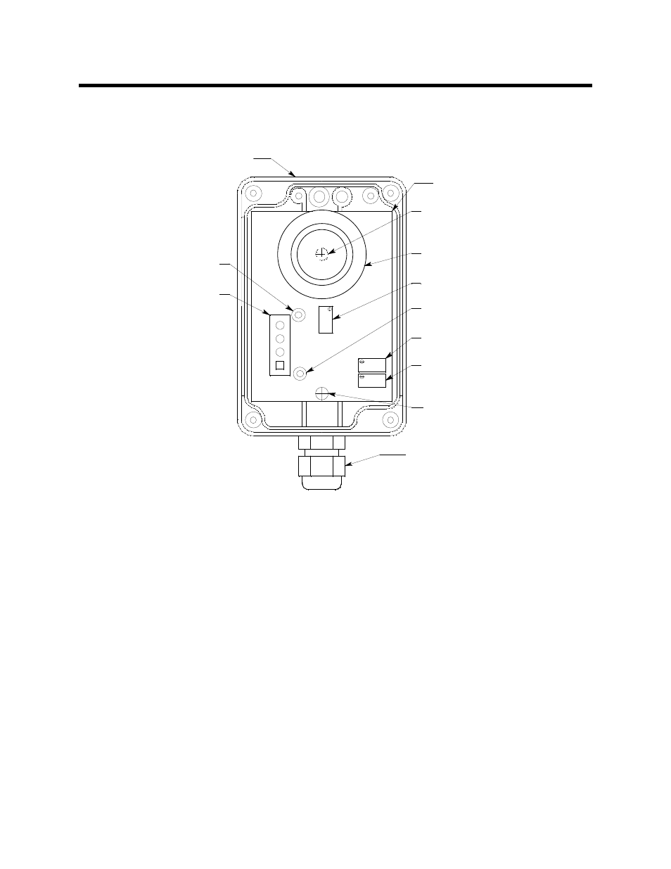
Figure 1: H
2
S Transmitter Component Location
H
2
S Sensor
The sensor is cylindrical with the sensing face on the top and the connection pins on the
bottom. The sensor plugs into the amplifier PCB with the four pins. The sensor is exposed
to the ambient air through an opening in the enclosure cover. Through a series of chemical
and electrical reactions, the sensor produces an electrical output that is proportional to the
detection range of the transmitter.
Sealing Spacer
The ring shaped plastic sealing spacer fills a gap in the rubber boot that is installed on the
sensor. The rubber boot is used to seal the sensor to the enclosure cover in both the CO
and H
2
S transmitters. In the CO transmitter the rubber boot also retains a charcoal filter.
Since a charcoal filter is not used in the H
2
S transmitter, the sealing spacer fills the space
that would be filled by the charcoal filter’s body.
Amplifier PCB
The amplifier PCB converts the electrical output from the sensor to a 4 to 20 mA signal
(that is proportional to the detection range) and transmits the signal to a gas monitoring
controller. The amplifier PCB includes the interconnect terminal strip, sensor sockets, span
pot, zero pot, and test points (see Figure 1).
Amplifier PCB
Zero Pot
Span Pot
Test Point CAL-
Factory Set Pot
Amplifier PCB Mounting
Screw (under sensor)
Cable Bushing
Amplifier PCB
Mounting Screw
R
CAL-
TB1
CAL+
+V
FB
B
SPAN
Enclosure
(shown w/out cover)
Interconnect
Terminal Strip
Test Point
CAL+
ZERO
Sensor (w/sealing
spacer & boot)