Description, Infrared co, Detector – RKI Instruments 65-2391RK User Manual
Page 6
2 • 65-2391RK CO
2
Transmitter
Description
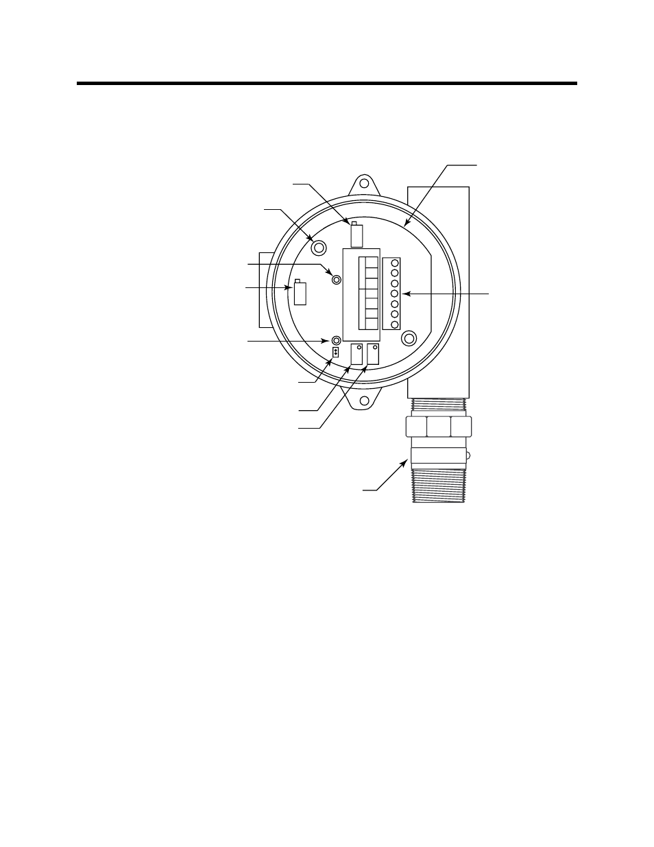
This section describes the components of the CO
2
transmitter. The transmitter is a 4 - 20
mA type detector head. It consists of the infrared CO
2
detector, amplifier, and junction
box.
Figure 1: CO
2
Transmitter Component Location
Infrared CO
2
Detector
The infrared CO
2
detector is made up of a miniature infrared CO
2
detector housed and
encapsulated in a pipe nipple. The pipe nipple has 3/4 inch NPT threads on each end and
a 1 1/4 inch hex that allows removal or installation of the detector with a wrench. A
porous flame arrestor that is coated with a hydrophobic film that repels liquids is on one
end of the detector and allows sample gas to enter the detector. Four color coded leads,
red, white, green, and black, extend from the other end of the detector. The leads allow
you to connect the detector to the amplifier.
To distinguish the different ranges of CO
2
detectors from one another, a short length of
shrink tubing is applied to the wiring where it comes out of the nipple. The following
table indicates the color of the shrink tubing and the color of the wire to which it is
applied.
GND
24V
4-20
RED
WHT
GRN
BLK
SENSOR
POWER/SIG
TP+
TP-
Amplifier
Interconnect
terminal strip
Test point (-)
Securing screw (2)
Test point (+)
Zero potentiometer
Span potentiometer
Potentiometer
(factory set)
Potentiometer
(factory set)
Jumper pins
(factory use only)
IR CO Detector
2