RKI Instruments 65-2391RK User Manual
Page 15
65-2391RK CO
2
Transmitter • 11
Replacing Components of the CO
2
Transmitter
This section includes procedures to replace the IR CO
2
detector and amplifier.
Replacing the IR CO
2
Detector
1.
Turn off power to the controller.
2.
Place the controller’s power switch in the OFF position.
3.
Remove the junction box cover.
4.
Disconnect the detector leads from the interconnect terminal strip. Note the position
of the color-coded leads as you remove them.
5.
Unscrew the detector from the junction box.
6.
Guide the detector leads of the replacement detector through the bottom conduit hub
of the junction box, then screw the mounting threads of the detector into the conduit
hub.
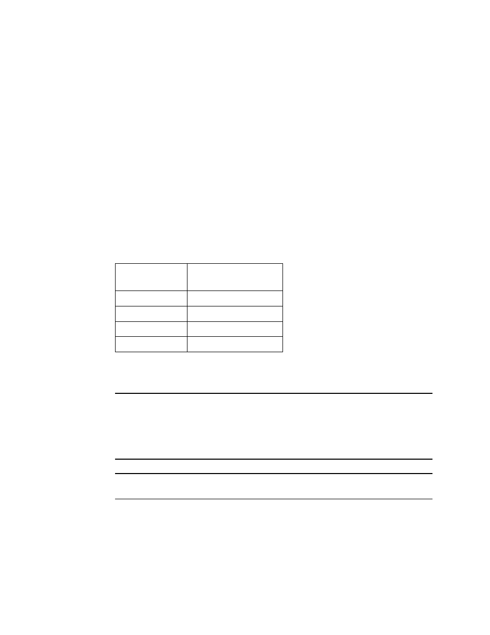
7.
Connect the detector leads to the interconnect terminal strip as shown in Table 4
below and Figure 3 on page 6 of this manual.
8.
Turn on power to the controller.
9.
Place the controller’s power switch in the ON position.
NOTE:
When first powered up, the transmitter will enter about a one minute period
when the 4-20 mA output is stabilizing and may be above the controller alarm
points or well below zero momentarily. RKI controllers have a one minute
warmup period when the controller does not display any gas reading or give any
alarm indication. The CO
2
transmitter’s 4-20 mA signal should be stable by the
time the controller’s warmup period is over.
CAUTION:
Allow the replacement detector to warm up for 5 minutes before you continue with
the next step.
10. Calibrate the replacement detector as described in “Calibration” on page 13 of this
manual.
Replacing the Amplifier
1.
Turn off power to the controller
2.
Place the controller’s power switch in the OFF position.
Table 4:
Reconnecting the CO2
Detector to the Amplifier
Detector Lead
Amplifier Interconnect
Terminal Strip
Red
RED
White
WHT
Green
GRN
Black
BLK