RKI Instruments 65-2391RK User Manual
Page 16
12 • 65-2391RK CO
2
Transmitter
3.
Remove the junction box cover.
4.
Disconnect the detector leads from the interconnect terminal strip.
5.
Disconnect the wiring that connects the CO
2
transmitter to the controller from the
amplifier’s interconnect terminal strip.
6.
Unscrew and remove the two screws that secure the amplifier to the junction box.
The screws are at the top left and bottom right of the amplifier.
7.
Remove the amplifier.
8.
Place the new amplifier in the same position as the amplifier you removed in the
previous step.
9.
Use the two screws you removed in step 6 to secure the amplifier to the junction box.
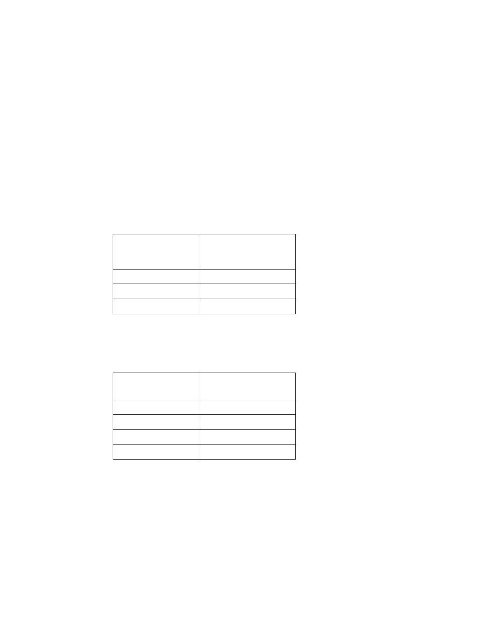
10. Reconnect the wiring that connects the controller to the CO
2
transmitter at the
amplifier’s interconnect terminal strip as shown in Table 5 below and Figure 3 on
page 6 of this manual.
11. Reconnect the detector leads to the amplifier’s interconnect terminal strip as shown in
Table 6 below and Figure 3 on page 6 of this manual.
12. Turn on power to the controller.
13. Turn on the controller and place it into normal operation.
Table 5:
Reconnecting the CO
2
Amplifier
to the Controller
Amplifier Interconnect
Terminal Strip
Controller
Transmitter Terminal
Strip (typical)
GND
- (DC -)
4-20
4 - 20 mA (FB or S)
24V
+ 24V
Table 6:
Reconnecting the CO
2
Detector to the Amplifier
Detector Lead
Amplifier Interconnect
Terminal Strip
Red
RED
White
WHT
Green
GRN
Black
BLK