Start up, Introducing incoming power, Controller transmitter terminals,typical – RKI Instruments 65-2391RK User Manual
Page 10
6 • 65-2391RK CO
2
Transmitter
9.
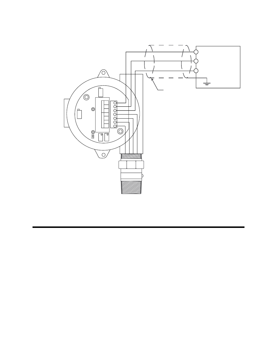
Connect the wires to the applicable transmitter terminal strip at the controller as
shown in Figure 3 below.
Figure 3: Wiring the CO
2
Transmitter to a Controller
10. If shielded cable is used, connect the cable’s drain wire to an available chassis ground
at the controller.
Start Up
This section describes procedures to start up the CO
2
transmitter and place the transmitter
into normal operation.
Introducing Incoming Power
1.
Complete the installation procedures described earlier in this manual.
2.
Verify that the power wiring to the controller is correct and secure. Refer to the
controller operator’s manual.
3.
Turn on or plug in power to the controller, then place the controller’s power switch in
the ON position.
4.
Verify that the controller is on and operating properly. Refer to the controller
operator’s manual.
GND
24V
4-20
RED
WHT
GRN
BLK
SENSOR
POWER/SIG
TP+
TP-
Black
Green
White
Red
Controller Transmitter
Terminals,Typical
- (DC -)
+ 24 VDC
4 - 20 mA In (FB or S)
Cable Shield