Co detector – RKI Instruments 65-2335RK User Manual
Page 7
65-2335RK CO Transmitter • 3
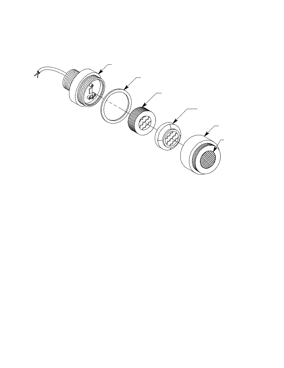
CO Detector
The CO detector includes the detector housing body, detector housing, cap, cap gasket,
plug-in sensor, and charcoal filter.
Figure 2: Oxygen Detector Component Location
Detector Housing Body
The detector housing body protects the electronic components within the housing. Use the
mounting threads at the top of the detector housing to screw the CO detector into a 3/4”
NPT hub on the bottom of the junction box. Two wires extend from the top of the detector
housing body. Use these wires to connect the CO detector to the amplifier. One of the
wires is black and one of the wires is red.
The housing body includes a four-socket pattern at the bottom of the housing body. This
socket pattern accepts the sensor’s four pins to secure the sensor within the detector
housing. A pre-amplifier, located between the sockets and the two interconnect wires,
conditions the sensor’s signal before the signal reaches the controller.
Housing Cap & Cap Gasket
The housing cap screws onto the detector housing. It retains the sensor and the rubber
boot with the charcoal filter and protects them from damage. A hydrophobic membrane
on the outside of the cap face keeps water and particulates away from the charcoal filter
and sensor face behind the cap. Unscrew the detector cap to access the charcoal filter and
sensor for maintenance or replacement. A cap gasket seals the interface between the
housing and cap.
Plug-In CO Sensor
The plug-in sensor is secured in the detector assembly by the housing cap. Through a
series of chemical and electrical reactions, the sensor produces an electrical output that
corresponds to the detection range of the detector.
Hydrophobic
Membrane
CO Plug-in Sensor
Charcoal Filter
w/Rubber Boot
Detector Housing Body
Cap Gasket
Detector
Housing Cap