Parts list – RKI Instruments 65-2335RK User Manual
Page 19
65-2335RK CO Transmitter • 15
3.
Allow the gas to flow for two minutes, then verify that the reading matches the
response reading (± 2mV) you determined earlier. If necessary, use the span pot on the
amplifier to adjust the reading to match the correct response reading.
4.
Turn the regulator knob clockwise to close the regulator.
5.
Unscrew the regulator from the calibration cylinder.
Returning to Normal Operation
1.
Remove the voltmeter leads from the amplifier test points.
2.
Unscrew the calibration cup from the detector.
NOTE:
For convenience, leave the components of the calibration kit connected by the
sample tubing.
3.
Secure the junction box cover to the junction box.
4.
When the display reading falls below the alarm setpoints, return the controller to
normal operation.
5.
Verify that the controller display reading decreases and stabilizes at 0 ppm.
6.
Store the components of the calibration kit in a safe and convenient place.
Parts List
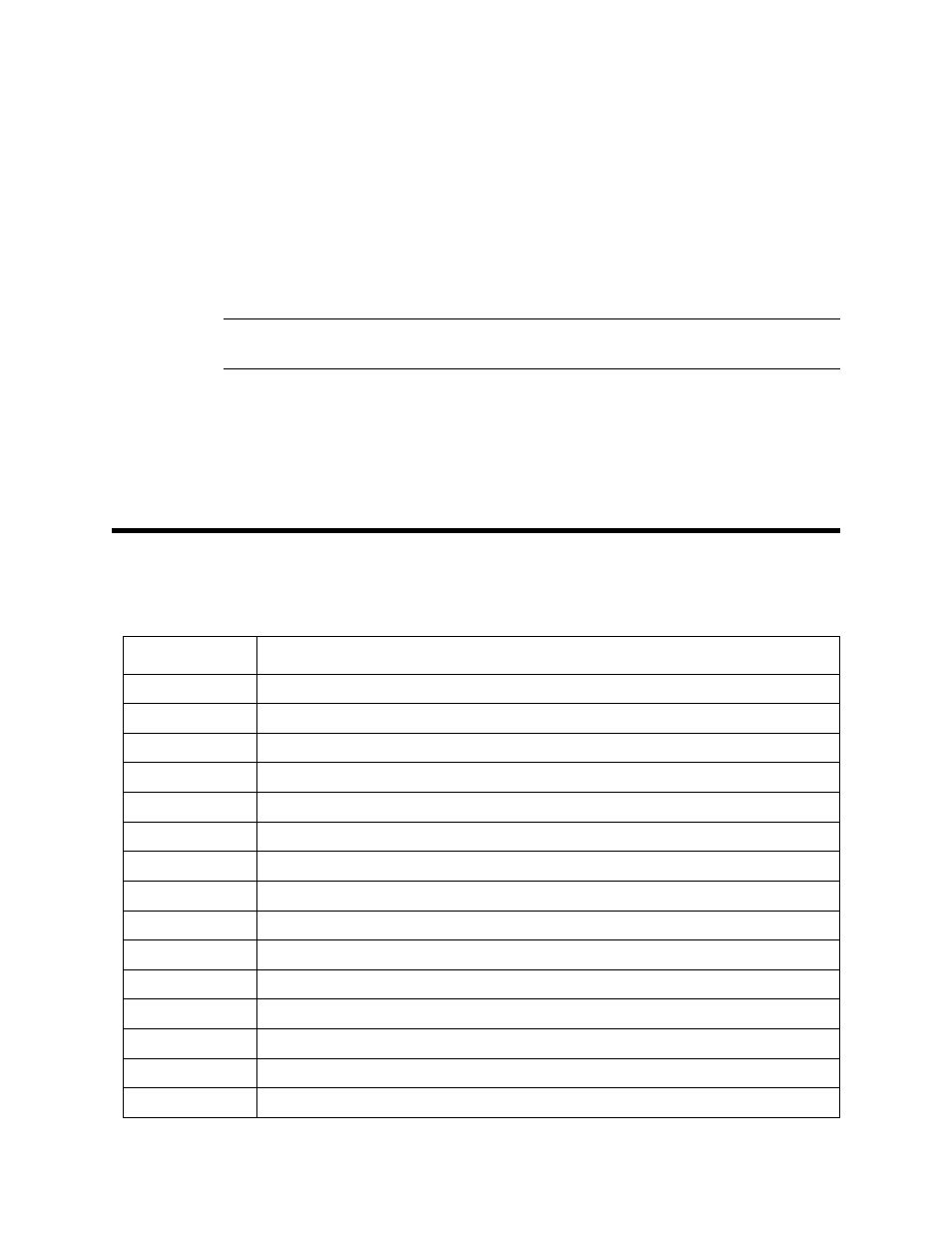
Table 3 lists replacement parts and accessories for the CO transmitter.
Table 3: Parts List
Part Number
Description
06-1248RK
Calibration kit sample tubing, 3 foot length
07-0039RK
Detector housing cap gasket
07-0203RK
Rubber retaining boot (for charcoal filter)
18-0405RK
Junction box (without cover; pre drilled for amplifier)
18-0406RK
Junction box cover
33-7101RK
Charcoal filter disk
57-1064RK-03
Toxic amplifier with orienting gasket
65-2335RK
CO transmitter, non-explosion proof, includes detector and amplifier
65-2496RK
CO replacement detector, includes sensor
71-0177RK
65-2335RK Operator’s Manual (this document)
81-0064RK-01
Calibration cylinder (50 PPM CO in air; 34 liter steel)
81-0076RK-01
Zero air calibration cylinder, 34 liter steel
81-1003RK
Regulator (for 34 liter steel calibration cylinders)
81-1117RK
Calibration cup
ES-1531-CO
CO replacement sensor