Calibrating infrared methane sensors – RKI Instruments Eagle 1 Manual User Manual
Page 77
Eagle Instruction Manual
Appendix E: Infrared Methane Sensors • 70
these models, the infrared methane sensor is wired to the EC4 socket
on the analog PCB and the gas reading is displayed in channel 1. This
sensor is also capable of measuring in the PPM range.
Eagles with an infrared methane sensor that has a 0 to 100% Volume
CH
4
range may also include the standard combustible gas sensor.
Table 14 lists the sensor configuration for Eagles that include this
sensor. Not all channels may be active in your Eagle.
Calibrating Infrared Methane Sensors
Recommended calibration frequency for the infrared methane sensor
is once every 3 months. Enter Calibration mode and calibrate the
infrared methane sensor using the same procedure as the standard
combustible gas sensor (see “Calibration” on page 42).
NOTE:
The 0 to 100% Volume CH
4
version of the infrared methane
sensor requires the use of a sample bag due to the type of
calibration cylinder used. See Table 15 on page 71 for ordering
information.
Adjusting the Sensor Controls
CAUTION:
Only perform the following steps if you are unable to set the
correct calibration reading with the AIR/
▲
and SHIFT/
▼
buttons.
1. Use the AIR/▲ and SHIFT/▼ buttons to set the reading to the
middle of the range in which you can currently adjust the reading.
For example, if you can set the reading from a minimum of 10%
LEL to a maximum of 40% LEL, set the display to 25% LEL.
2. Unscrew the two large screws on the top of the case, then carefully
lift the top of the case and lay it aside.
3. Locate the infrared methane sensor in the front half of the bottom
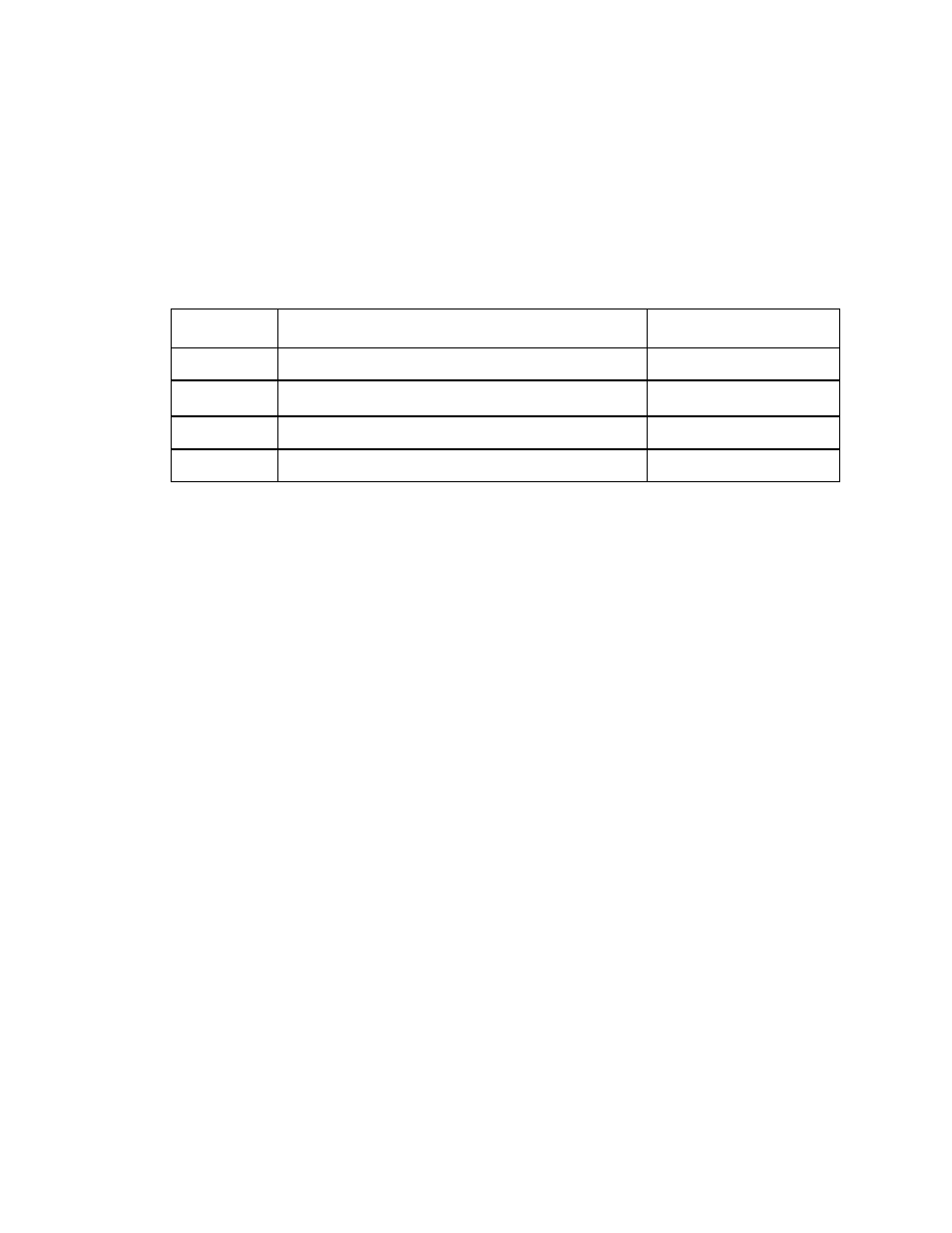
Table 14: Sensor Configuration for Infrared Methane Sensors
(0 to 100% Volume)
Channel
Sensor
Analog PCB Socket
1
Standard combustible gas (0 to 100% LEL)
COMB
2
Infrared methane (0 to 100% Vol. CH
4
)
EC4
3
Oxygen
CN2
4
Toxic gas or infrared carbon dioxide
EC1, EC2, or EC3