Alarm adjust mode – RKI Instruments RI-215A User Manual
Page 18
18 • Alarm Adjust Mode
RI-215A
Operator’s Manual
So if the alarm relay contacts are wired to turn on a ventilation system when the
concentration of CO
2
reaches the alarm point (e.g., 1000 ppm), the ventilation system will
remain on until the concentration of CO
2
falls to 50 ppm below the alarm point (e.g., 950).
Alarm Adjust Mode
Use the Up (
∆)
switch to enter Alarm Adjust Mode.
Verifying the Alarm Point
Three ranges of gas detection are available for the RI-215A: 0 - 2,000 ppm, 0 - 5,000 ppm,
and 0 - 9990 ppm. Detection ranges are set at the factory. When you ordered the RI-215A,
you should have specified one of these gas detection ranges for your unit.
The alarm point of the RI-215A is also set at the factory (e.g., 1000 ppm). To display the
current alarm point from the normal LCD, do the following:
1. Press and hold the Up (
∆)
switch. The alarm point appears (e.g., 10:00) on the LCD
(alarm verification screen). In this example, 10:00 indicates an alarm point of 1000
ppm. Note that the colon (:) will be flashing.
2. Release the Up (
∆)
switch to return to the normal LCD. Do not hold the (
∆)
switch for
more than three seconds or the unit will display the Alarm Adjust screen.
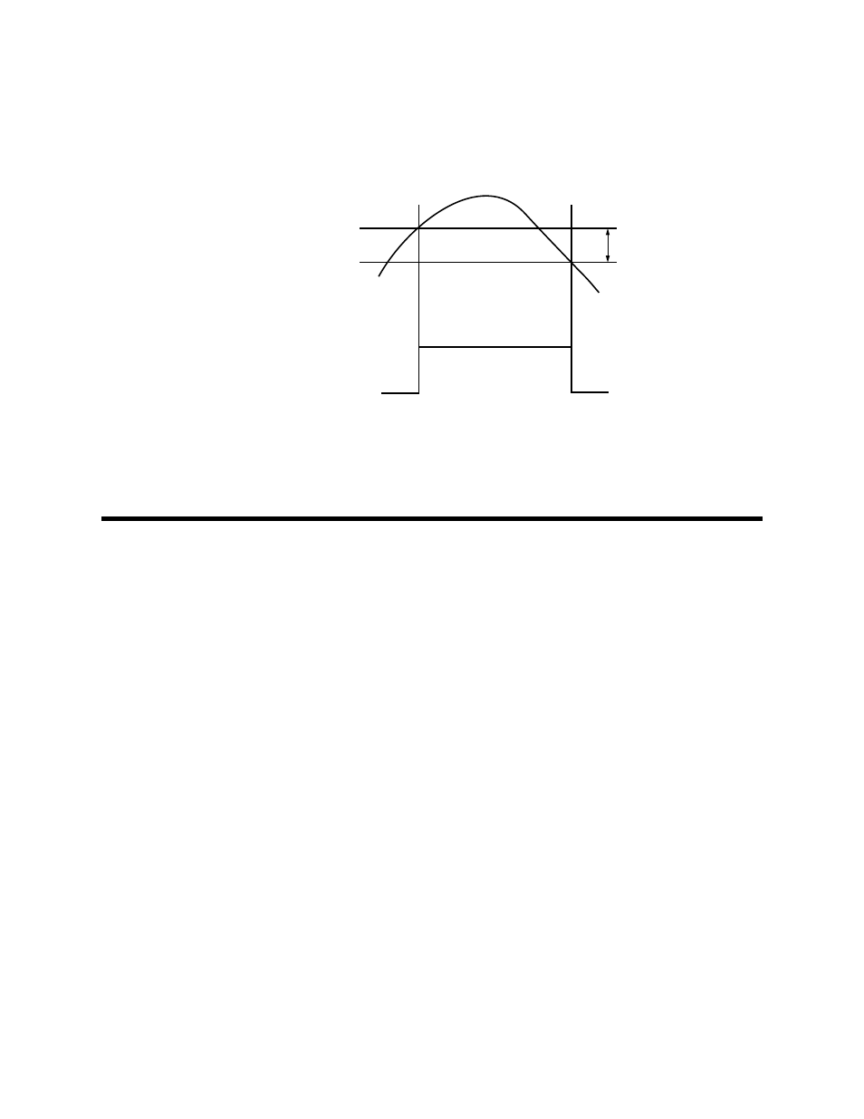
Further note that the RI-215A’s alarm relay has a built-in hysteresis (lag) of 50 ppm. After
the alarm point has been reached (e.g., 1000 ppm), the alarm relay will activate. As the
CO
2
concentration begins to fall, the alarm relay will deactivate 50 ppm below the
activation point (e.g., 950 ppm). The 50 ppm hysteresis keeps the alarm contacts from
“chattering” should the CO
2
concentration hover around the alarm point.
1000 ppm
950 ppm
Hysteresis
50 ppm
CO
2
Relay contact
Figure 6: Model RI-215A’s Built-in Hysteresis of 50 ppm
Closed
Open
Open