Wiring the ri-215a – RKI Instruments RI-215A User Manual
Page 12
12 • Wiring the RI-215A
RI-215A
Operator’s Manual
Wiring the RI-215A
This section describes procedures to connect power to the RI-215A. This section also
describes optional procedures to connect a controller or recorder and external alarm
device to the RI-215A.
WARNING: To reduce the risk of electric shock, always verify that power to the RI-
215A has been turned off before making any wiring connections to the RI-
215A. Make sure to operate the RI-215A from the specified power voltage of
24VAC/VDC, and follow the local electric code when making all electrical
connections.
Notes on Wiring the RI-215A
•
Use a stable 24 VAC or 24 VDC power source. Do not use a noisy power source. If the
power source is noisy, use a line filter to eliminate the noise.
•
Use shielded cable for the output signal line in cases where noise is a potential
problem.
•
The alarm relay contacts in the RI-215A are rated at 0.5A, 125 VAC. Do not use these
contacts to control an electrical load larger than this rating. For large load control, use
the RI-215A alarm contacts to control a slave relay with an appropriate contact rating.
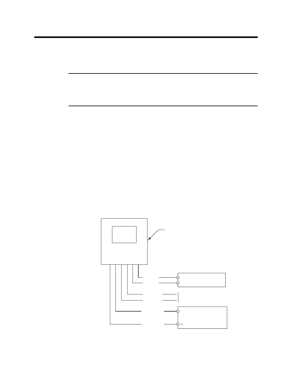
Figure 3 below shows the general wiring diagram of the RI-215A, and is not specific to
any device to which the unit could be connected. The red wires of the cable assembly, as
shown in Figure 3 below, connect to an external 24 VAC or 24 VDC power supply. The
white wires serve as a relay contact and can be used to control an external alarm. The
yellow and blue wires carry a 4 - 20 mA output signal. These wires can be connected to a
gas monitoring controller or a recording device.
RI-215A
1 (red)
2 (red)
3 (white)
4 (white)
5 (yellow)
6 (blue)
24 VAC or 24 VDC
Power
Normally Open
Relay Contact
Recording Device
+
4 - 20 mA Standard, 0 - 10V Optional
Figure 3: General Wiring Diagram of the RI-215A