RKI Instruments RI-215A User Manual
Page 13
RI-215A
Operator’s Manual
Wiring the RI-215A • 13
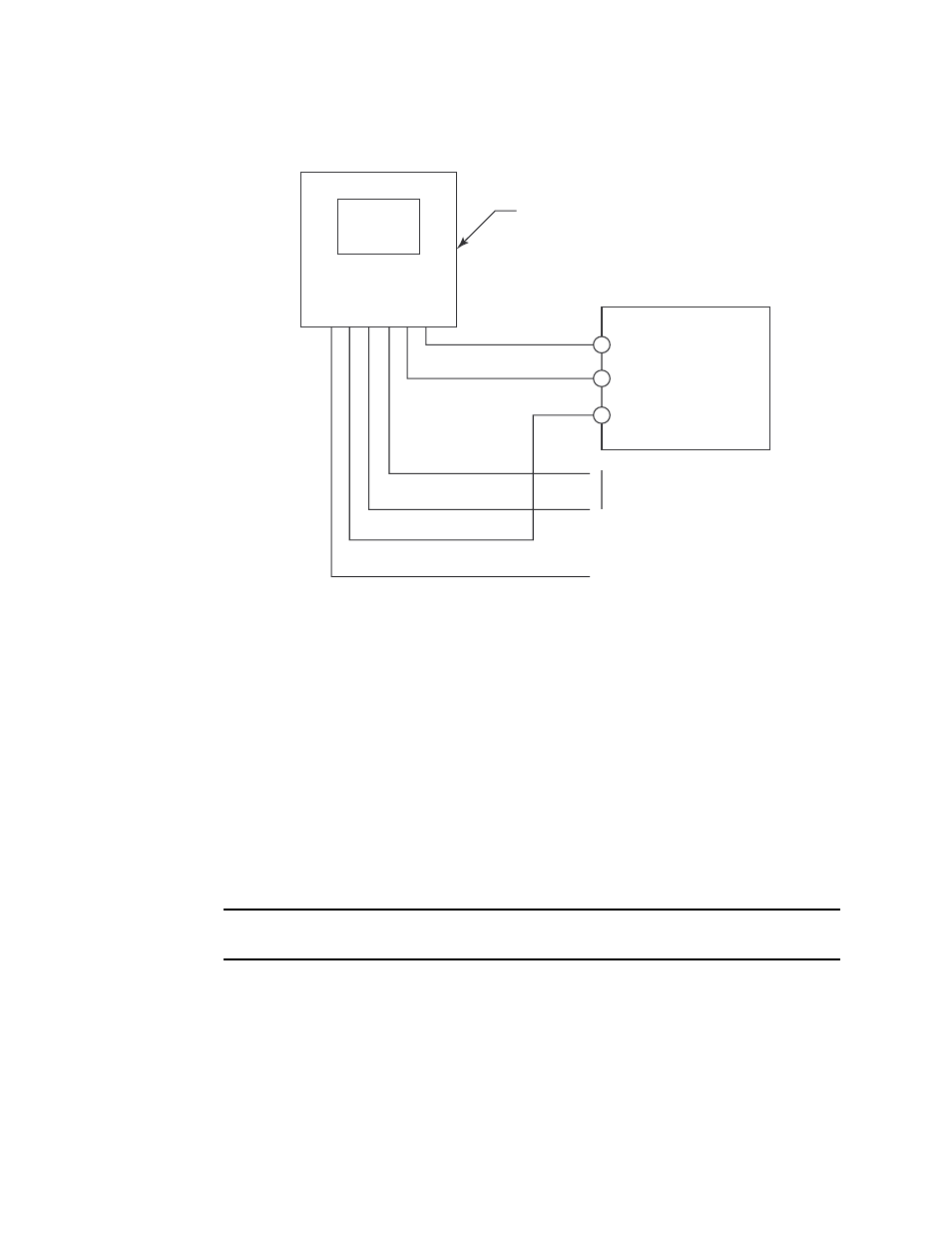
Figure 4 below shows how to wire the RI-215A to a controller that accepts 3-wire, 4-20 mA
transmitters.
Connecting Power
1. Verify that power to the RI-215A has been turned OFF.
2. Connect the two red AC line cables to the 24 VAC or 24 VDC power source. Refer to
the wiring diagram in Figure 3 on page 12.
3. If you do not plan to make any more wiring connections, then terminate the
remaining cables appropriately to avoid an electrical short.
Connecting the RI-215A to a Recorder
Perform the following procedure to connect the RI-215A to a recorder. The output of the
RI-215A is a 4-to-20 mA signal, which is proportional to the detection range.
NOTE: The standard output of the RI-215A is 4 - 20 mA. An optional output of 0 -10 V is
available and must be specified at the time of your order.
1. Verify that power to the RI-215A has been turned OFF.
2. Connect the yellow (+) and blue (-) wires to the controller or recording device. Refer to
the wiring diagram in Figure 3.
3. If you do not plan to make any more wiring connections, then terminate the
remaining wires.
RI-215A
1 (red)
2 (red)
3 (white)
4 (white)
5 (yellow)
6 (blue)
Controller Terminals
+ 24 VDC
- (DC Ground)
4 - 20 mA In (S or FB)
Normally Open
Relay Contact
Not Used
Figure 4: Wiring Diagram of the RI-215A as a 3-Wire 4-20 mA Transmitter