Practical instrument electronics, Reading milliamp outputs, Read dc volts – Practical Instrument Electronics 434 User Manual
Page 6: Read, 3) select “read” using slide switch
Practical Instrument Electronics
82 East Main Street Suite 3.14 • Webster, NY 14580 Tel: 585.872.9350 • Fax: 585.872.2638 • [email protected] • www.piecal.com
Page 6
Signals exceeding ±60.00 VDC are indicated
by i on the display.
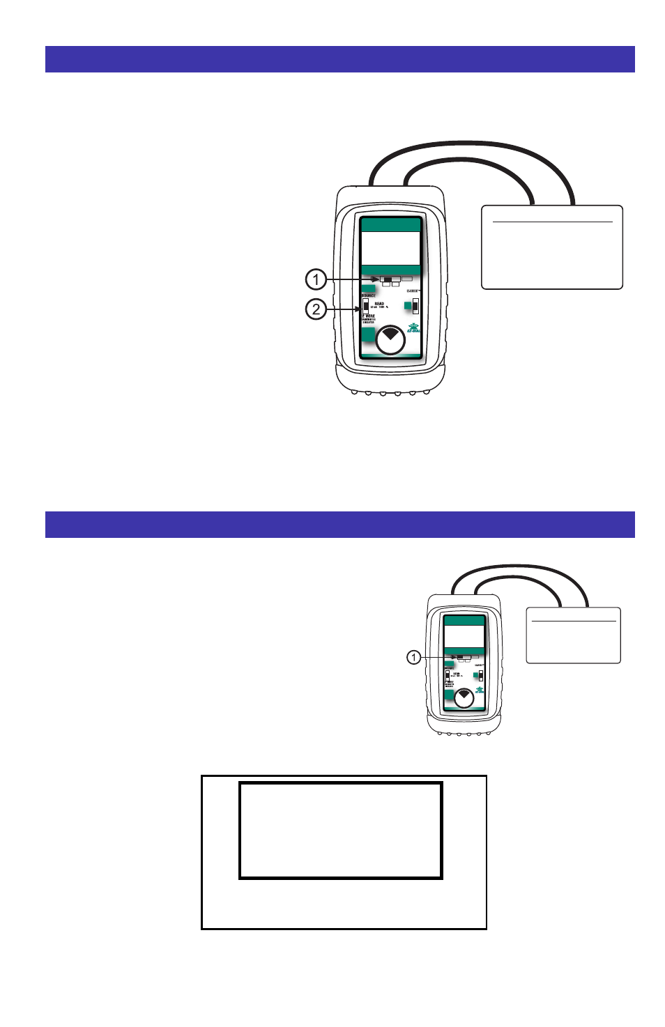
Reading Milliamp Outputs
Power 2 Wire
Transmitters
Dial Output to
FULL SCALE to
Power 2 Wire
Transmitters
DIAL
AUTOMATED DIAGNOSTIC CALIBRATOR
4-20 mA
Push & Hold
to
Store/Step
Push & Turn
for
Fast Dialing
Double Click
for Options
VDC
%mA
mA OFF
100%
0%
4.340
READ
mA
Milliamp Output Signal
Controller
Transmitter
P/I
DCS
READ V
Choose this function to measure from -99.99 to +99.99V DC.
1) Select
“VDC” with slide switch
q
.
2) Connect the red (+) and black (-) leads of the PIECAL 434
across the voltage source to be measured.
Any DC voltage from -60.00 to +60.00 volts may be
measured. Loop power supplies, signal voltages at receivers,
batteries and transmitter voltage drops may be measured.
Signals exceeding ±60.00 VDC are indicated by i on the
display. Signals exceeding ±99.99 VDC will be indicated by
“OVERRANGE” flashing on the display.
Read DC Volts
Voltage to be Measured
Battery
Loop Power Supply
Transmitter Voltage Drop
1 to 5 Volt Loops
Power 2 Wire
Transmitters
Dial Output to
FULL SCALE to
Power 2 Wire
Transmitters
DIAL
AUTOMATED DIAGNOSTIC CALIBRATOR
4-20 mA
Push & Hold
to
Store/Step
Push & Turn
for
Fast Dialing
Double Click
for Options
VDC
%mA
mA OFF
100%
0%
24.34
READ
V
READ
i
72.83
V
READ mA, READ % (Percent of 4 to 20 mA)
Choose this function to measure from 0.000 to 24.000 milliamps or -25.00 to 125.00%.
1) Open the current loop at any conve-
nient point along the signal path.
2) Select “mA” or “% 4 to 20mA” with slide
switch
q
.
3) Select “Read” using slide switch
w
.
4) Connect the red input lead (+) of the
PIECAL 434 to the more positive point
of the break and the black input to the
more negative point.
Signals below 0 mA or open circuits are
indicated by 0.000 mA (-25.00%) on the
display. Signals above 52 mA are current
limited by protection circuitry and
“OVERRANGE” is flashed on the display.