Warnings, 3 warnings – PLX Devices DM-200 OBDII User Manual
Page 21
Users Guide: iMFD User Guide
Version 1.0 Jan 1, 2008
www.plxdevices.com
(408)745-7591
21
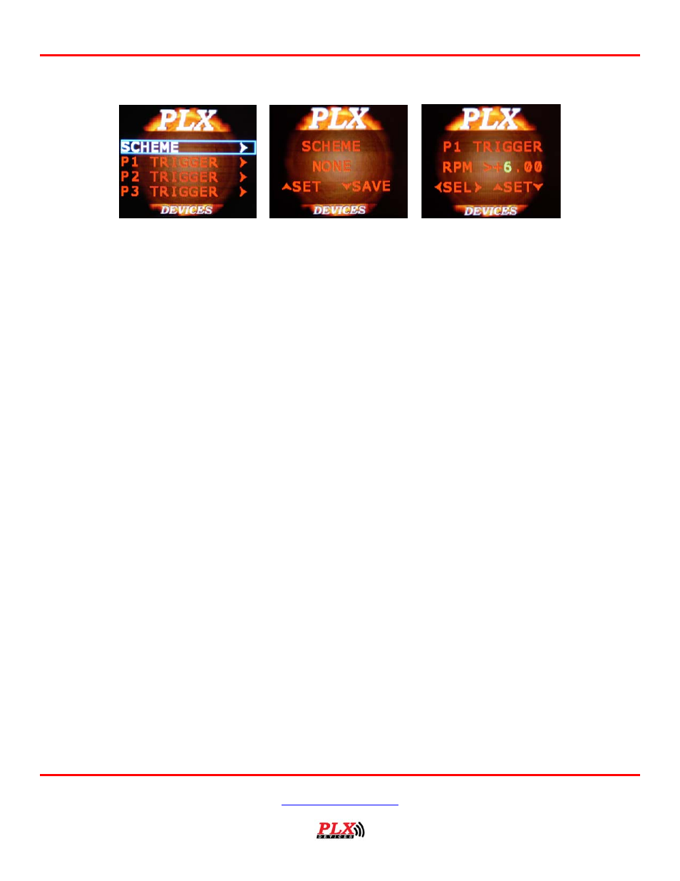
7.3 Warnings
The DM-200 can monitor up to 4 parameters for warnings. The DM-200 monitors 4 parameters
simultaneously and evaluates if any trigger points have been exceeded. If any of the 4 parameter trigger
points have been exceeded then the DM-200 will evaluate if a warning message should appear on the
display based on the “scheme” setting. To better explain this powerful feature, let’s look at an example.
Let’s say for example Parameter 1 is set to read AFR, Parameter 2 is set to read EGT, Parameter 3 is set
to read Oil Temperature and Parameter 4 is set to read Boost. The trigger points are set to the following.
Trigger point settings:
(Parameter 1) AFR > 15.0
(Parameter 2) EGT > 800
(Parameter 3) Oil > 110
(Parameter 4) BST > 15
Example:
If the DM-200 measures the following values and the “scheme” setting is set to P1 | P2, this means that if
the Parameter 1 is TRUE OR Parameter 2 is TRUE, a warning will trigger. Parameter 3 and 4 are ignored.
Measured values:
(Parameter 1) AFR = 14.0 FALSE
(Parameter 2) EGT = 850 TRUE
(Parameter 3) Oil = 105 FALSE
(Parameter 4) BST = 20 TRUE
Since Parameter 2 is TRUE, a warning will trigger according to the above example.
What will happen if the scheme is set to P1 & P2? This means that if Parameter 1 is TRUE AND Parameter
2 is TRUE, a warning will trigger. Since Parameter 1 is FALSE, a warning will not trigger. Parameter 3 and
4 are ignored.
What will happen if the scheme is set to P1 | P2 | P3 | P4? This means that if any parameter 1-4 is TRUE,
a warning will trigger. For this example, a warning will trigger.
What if the scheme is set to P1 & P2 & P3 & P4? This means that all parameter 1-4 must be true to trigger
a warning. For this example, a warning will not trigger.
Several other scheme combinations are available for you to fully customize your warnings as they work on
the same principal as the example above.