Basic engine information – Multiquip SP403030 User Manual
Page 22
PAGE 22 — MQ SP4030 SAW • OPERATION MANUAL — REV. #0 (01/22/09)
BASIC ENGINE INFORMATION
BASIC ENGINE COMPONENTS
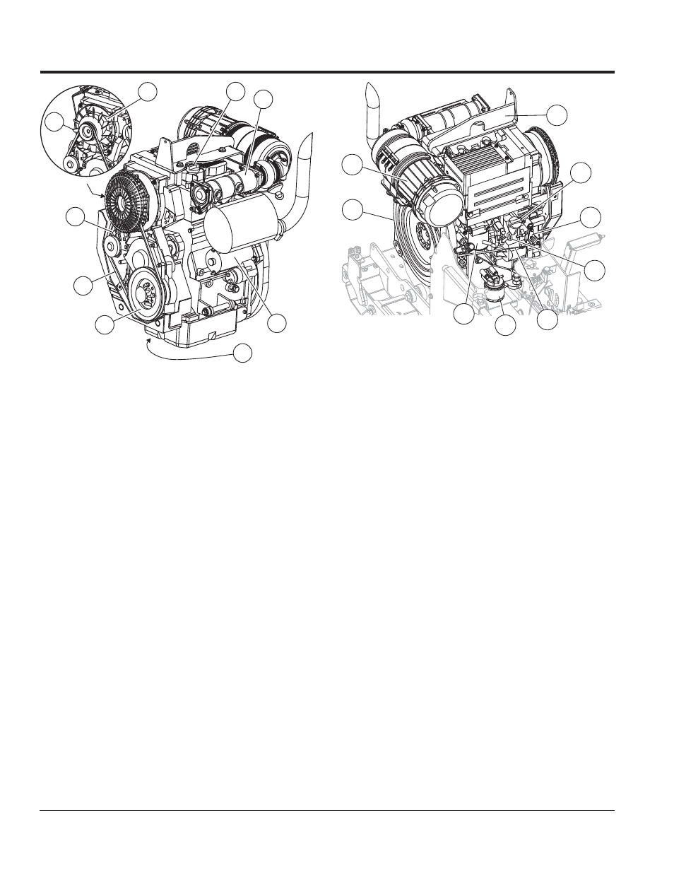
The following refer to basic engine components and their
functions that an operator may need to reference. The
manufacturer’s engine manual provides further instructions
and details of operation and servicing. The engine shown
in Figure 6 is a Deutz F2L2011 engine.
1. Fuel Filter — Removes dirt and water from the engine
fuel.
2. Governor Lever — This lever restricts engine speed
(high idle and low idle) through a speed control device
linked to the accelerator system.
3. Oil Dip Stick — Remove to check amount and
condition of oil in crankcase.
4. Oil Filter — Spin-on type, filters oil for contaminants.
5. Oil Drain Plug — Remove plug to drain crankcase
oil.
6. Oil Filler Port — Remove to add fresh crankcase oil.
7. Crankshaft V-Pulley — Check fan V-belt between V-
Pulley and fan to determine proper belt tension.
8. Cooling Fan — Driven by the V-belt, the cooling fan
cools the engine by cooling engine oil that circulates
through the engine block and cylinder head.
9. V-belt Tension Adjustment — This bolt provides
means to adjust the V-belt tension at the alternator
bracket.
10. V-belt (Fan belt) — Driven by the engine crank during
operation, drives the fan as well as the alternator.
11. Oil Fill Cap — Remove to add engine oil.
12. Lifting Eye — The lifting eye is provided if the removal/
installation of the engine becomes necessary.
13. Alternator — Located inside the fan assembly. Provides
current to the electrical system and charges the battery.
Driven by means of a crankshaft/V-belt pulley system.
14. Starter — Starts engine when ignition key is rotated
to the “START” position.
15. Flywheel — Main power is taken off from the flywheel
end.
16. Air Intake Port — Provides air from the air cleaner to
the turbocharger unit.
17. Throttle Cable — Provides direct control of engine
throttle lever from throttle control located on the console
control panel.
18. Air Cleaner Assembly — Provides clean filtered air
to the air intake port.
7
9
10
13
16
5
6
14
8
4
1
11
12
2
18
15
17
3
Figure 6. Basic Engine Components