Str46spvgh — controls and indicators – Multiquip STR46SPVGH User Manual
Page 16
PAGE 16 — HHN 31V
STR46SPVGH • RIDE-ON POWER TROWEL — OPERATION MANUAL — REV. #0 (07/17/08) — PAGE 16
27
22
22
31
30
29
25
26
28
23
24
20
21
21
20
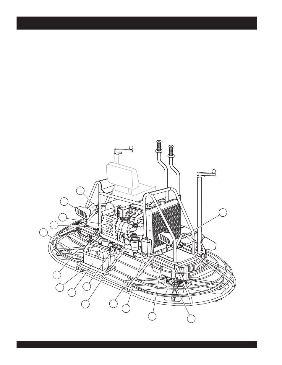
STR46SPVGH — CONTROLS AND INDICATORS
20. Oil Sight Glass
- Indicates the level of the hydraulic oil in
the gear box.
21. EZ- Mover Boss –
Front -side insertion point for EZ Mover.
Used when the transporting of the trowel is required.
22. Lift Loops –
Located on both the left and right sides of the
main frame. Used when the trowel must be lifted onto a
concrete slab.
23. Lights –
Four 12 volt halogen lights are provided with this
unit.
24. Right-Side Spider –
Consists (basic) of trowel arms,
blades, wear plate, and thrust collar etc.
25. Left-Side Spider –
Consists (basic) of trowel arms, blades,
wear plate, and thrust collar etc.
26. Belt Guard –
Encloses drive belt used in conjunction with
clutch.
30. Oil Filter –
Provides oil filtering for the engine.
31. Battery –
Provides +12V DC power to the electrical
system
Figure 4. STR46SPVGH Controls and Indicators (Rear)
27. Overflow Bottle -
Supplies coolant to the radiator when
radiator coolant level is low. Fill to indicated level as shown
on bottle.
28. Engine Air Filter –
Prevents dirt and other debris from
entering the fuel system. Lift locking latch on air filter
cannister to gain access to filter element.
29. Engine Dip Stick –
Indicates engine oil level. Add oil as
required.