Sth-55jd-tc — maintenance – Multiquip STH User Manual
Page 18
PAGE 18 — STH-10 FT. • RIDE-ON POWER TROWEL — PARTS & OPERATION MANUAL — REV. #5 (06/08/05)
STH-55JD-TC — MAINTENANCE
Sometimes it may be necessary to match blade pitch between
the two sets of blades. There are some signs that this may be
necessary. For example, the differences in pitch could cause a
noticeable difference in finish quality between the two sets of
blades. Or, the difference in blade pitch could make the
machine difficult to control. This is due to the surface area in
contact with the concrete (the blade set with the greater contact
area tends to stick to the concrete more).
Twin Pitch
Trowel blade pitch is controlled by rocker switches located on
the top of the left and right joystick handles. The rocker switch on
the left handle pitches only the left side blades. The rocker switch
on the right handle pitches blades on both the left and right
sides.
The left side rocker switch is used to "match" blade pitch of the
left and right sides. Once the two sides are "matched" (all blades
on both sides are completely flat), the right side rocker switch
may be used to pitch both sides simultaneously (Twin Pitch).
Important: just as with mechanical Twin Pitch, when using the
right side switch, if the blades on either side reach the maximum
or minimum pitch condition, both sides will
stop
pitching.
If the pitch angle is significantly different between the left and
right side blades, they must be "matched" (blades), using the left
side rocker switch. Always remember to use the left side rocker
switch first when matching the left and right blades. After both left
and right side blades have been matched then the right side
rocker switch (Twin Pitch) can be used.
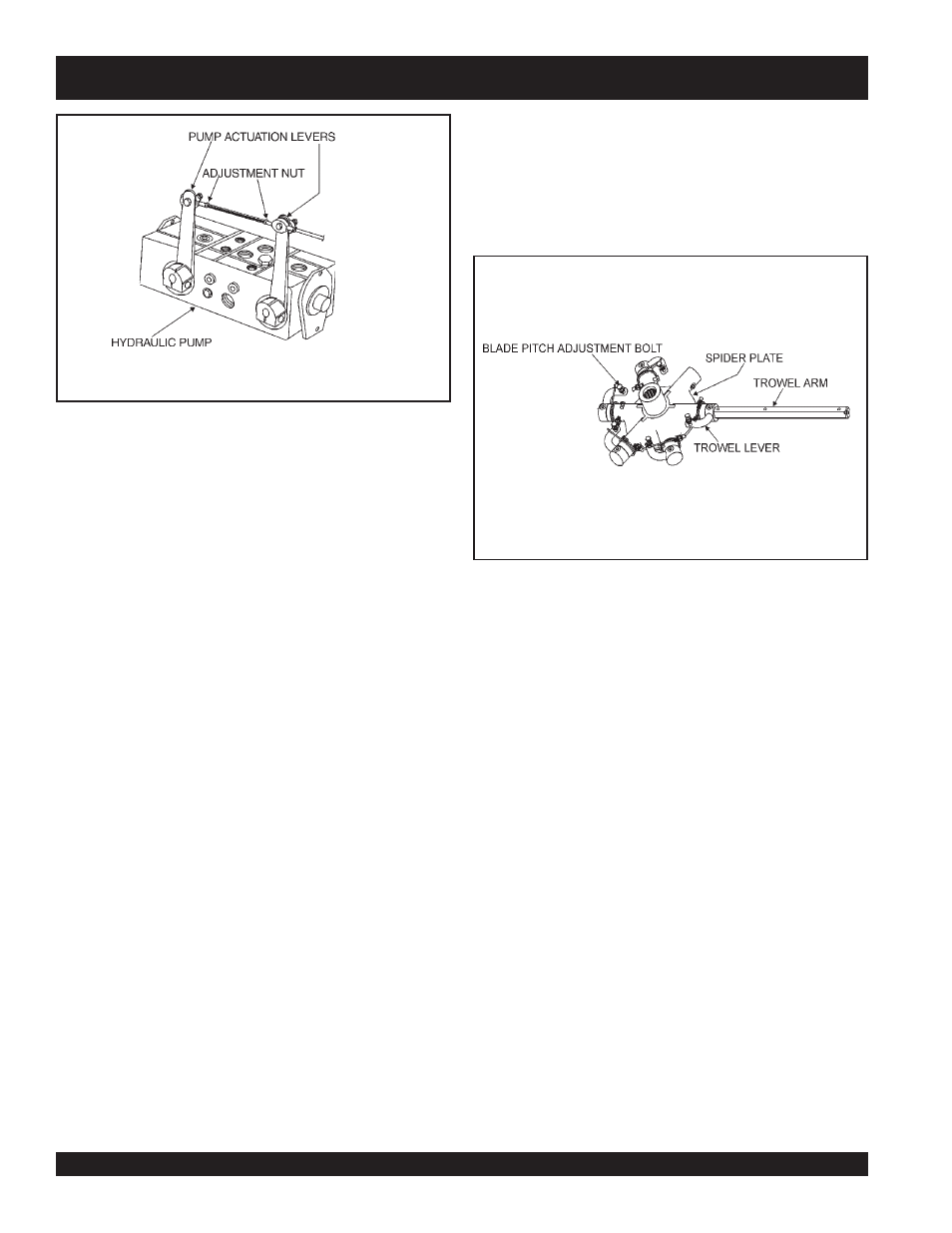
Figure 16. Pump Actuation
Levers/Speed Control Rod
Blade Pitch Adjustment Procedure
The maintenance adjustment of blade pitch is an adjustment
that is made by a bolt (Figure 17) on the arm of the trowel blade
finger. This bolt is the contact point of the trowel arm to the lower
wear plate on the thrust collar. The goal of adjustment is to promote
consistent blade pitch and finishing quality.
There are some things to look for when checking to see if
adjustment is necessary. Is the machine wearing out blades
unevenly (i.e. one blade is completely worn out while the others
look new)? Does the machine have a perceptible rolling or
bouncing motion when in use? Look at the machine while it is
running, do the guard rings “rock up and down” relative to the
ground? Do the pitch control cylinders rock back and forth? These
are some of the indications that the blade pitch may need to be
adjusted using the adjustment bolts on the trowel blade finger.
The easiest and most consistent way to make this adjustment is
to use the Trowel Arm Adjustment Fixture (P.N. 9177) . This fixture
will allow consistent adjustment of the trowel arm fingers. It comes
with all the hardware necessary to properly accomplish this
maintenance and instructions on how to properly utilize this tool.
Adjusting the trowel arm fingers without a fixture requires a special
talent.
If a trowel arm adjustment fixture is not available and immediate
adjustment is necessary; we suggest the following procedure.
If you can see or feel which blade is pulling harder, adjust the
bolt that corresponds to that blade. Another way to determine
which blades need adjustment is to place the machine on a
flat surface and pitch the blades as flat as possible. Now, look at
the adjustment bolts. They should all barely make contact with
the lower wear plate on the spider. If you can see that one of
them is not making contact; some adjustment will be necessary.
Figure 17. Blade Pitch Adjustment Bolt