Sth-55jd-tc — controls and indicators – Multiquip STH User Manual
Page 13
STH-10 FT. • RIDE-ON POWER TROWEL — PARTS & OPERATION MANUAL — REV. #5 (06/08/05) — PAGE 13
STH-55JD-TC — CONTROLS AND INDICATORS
17. Blade Pitch Control Switch (left side) - When the rocker
switch is pressed down and to the left it will cause less
pitch to be added to the left side blades only. Pressing the
rocker switch down and to the right will cause more pitch
to be added to the left side blades only. This switch will not
effect the right side blades for pitch.
18. Retardant Spray Control Button (right side) – When
pressed allows retardant spray to flow through the spray
nozzle located at the right front of the machine.
19. Retardant Spray Control Button (left side) – When
pressed allows retardant spray to flow through the spray
nozzle located at the left front of the machine.
20. Kill Switch – Shuts down engine when operator is not
sitting in seat .
21. Lights – Six Low voltage halogen lights are provided with
this unit.
22. Hydraulic Oil Filler Cap – Remove this cap to add
hydraulic oil.
23. Hydraulic Suction Filter – Filters hydraulic fluid prior to
pump inlet.
24. Hydraulic Oil Sight Glass - Indicates the level of the
hydraulic oil in the reservoir.
25. Engine Dip Stick – Indicates engine oil level. Add oil as
required.
26. Right Foot Pedal – Controls blade speed. Slow blade
speed is accomplished by slightly depressing the foot pedal.
Maximum blade speed is accomplished by fully depressing
the foot pedal.
27. Left Foot Riser – Operator foot rest pedal.
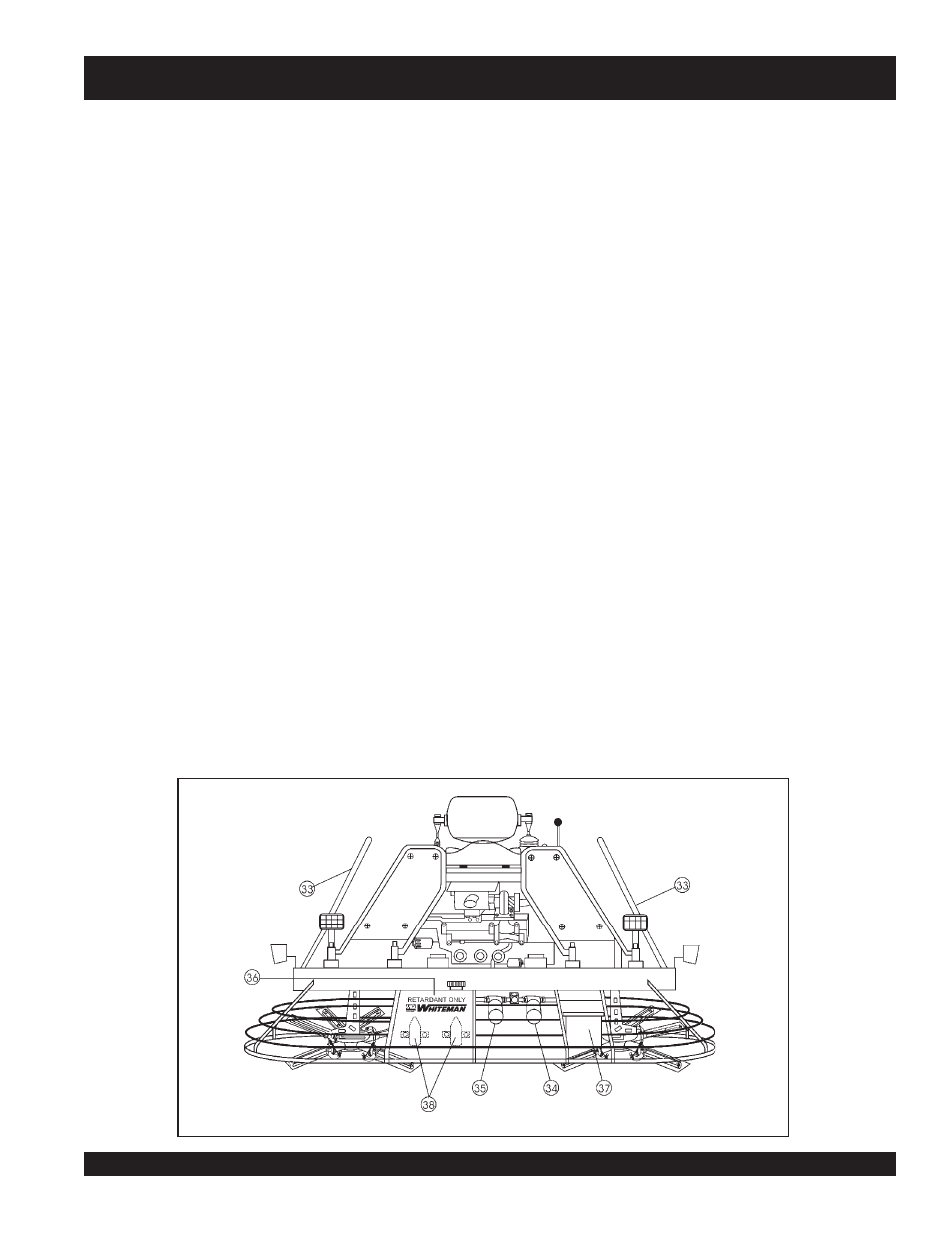
28. Fuel Gauge/Filler Cap - Indicates the amount of fuel in
the fuel tank. Remove this cap to add fuel.
29. Spray Nozzel – Spray nozzel for retardant. There are two
retardant spray nozzels supplied with this unit.
30. Engine Oil Filler Cap - Remove this cap to add engine oil.
31. Air Filter- Prevents dirt and other debris from entering the
engine.
32. Oil Filter- Provides oil filtering for the engine.
33. Lift Loops- Located on both the left and right sides of the
main frame. Used when the trowel must be lifted onto a
concrete slab.
34. Hydraulic Filter - Filters return oil flow from right
hydrostatic motor.
35. Hydraulic Filter - Filters return oil flow from left hydrostatic
motor.
36. Retardant Spray Tank - Holds 5 gallons of retardant
37. Battery - Provides +12V DC power to the electrical system
38. Retardant Spray Motors- Used in conjunction with the
left and right spray control buttons.
NOTE
Read this entire instruction manual completely before attempting
to operate this machine.
The following section is intended as a basic guide to the ride-on
trowel operation, and is not to be considered a complete guide
to concrete finishing. It is strongly suggested that all operators
(experienced and novice) read “
Slabs on Grade
” published by
the American Concrete Institute, Detroit Michigan.
Figure 3. STH Controls and Indicators (Rear)