Maintenance, Clean-up, Trowel arm adjustment procedure – Multiquip JWN24HSCSL User Manual
Page 31
JWN-SeRIeS RIDe-ON pOWeR TROWeL • OpeRaTION maNuaL — Rev. #1 (05/12/12) — page 31
Maintenance
Clean-up
Never allow concrete to harden on the power trowel.
Immediately after use wash any concrete off the trowel
with water, be careful not to spray a hot engine or muffler.
An old paint brush or broom may help loosen any concrete
that has started to harden.
Trowel arm adjustment procedure
A level, clean area to test the trowel prior to and after
adjustment is essential. Any unlevel spots in the floor
or debris under the trowel blades will give an incorrect
perception of adjustment. Ideally, a 5' x 5' three-quarter
inch thick flat steel plate should be used for testing.
1. To determine which blades need adjustment, place the
trowel in the test area (three-quarter inch thick plate)
and look for the following conditions:
• Pitch the blades as flat as possible and look at the
adjustment bolts. They should all barely make contact
with the lower wear plate on the spider. If you can
see that one of them is not making contact, some
adjustment will be necessary.
• Is the machine wearing out blades unevenly (i.e. one
blade is completely worn out while the others look
new)?
NOTICE
The following procedure should be followed to adjust
trowel arms when it becomes apparent that the trowel
is finishing poorly or in need of routine maintenance.
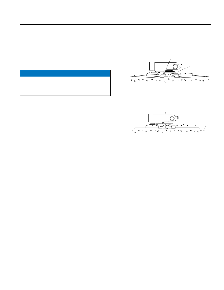
Figure 26 illustrates "worn spider bushings or bent trowel
arms". Check to see that adjustment bolt is barely touching
(0.10" max. clearance) lower wear plate. All alignment bolts
should be spaced the same distance from the lower wear
plate.
Figure 26. Worn Arm Bushings
Figure 27 illustrates the "correct alignment " for a spider
plate (as shipped from the factory).
Figure 27. Correct Spider Plate Alignment
2. Start engine, and bring trowel blades up to full speed
and look for the following conditions:
• Does the trowel have a perceived rolling or bouncing
motion?
• Does the guard ring “rock up and down” relative to
the ground?
SURFACE
LOWER
WEAR
PLATE
“DISHED” EFFECT ON
FINISHED CONCRETE
ADJUSTMENT
BOLT
INCORRECT
ALIGNMENT
ARM
GEARBOX
SURFACE
BLADE
MOUNTING
BAR
CORRECT ALIGNMENT
BLADES ARE FLAT