Components – Multiquip JWN24HSCSL User Manual
Page 16
page 16 — JWN-SeRIeS RIDe-ON pOWeR TROWeL • OpeRaTION maNuaL — Rev. #1 (05/12/12)
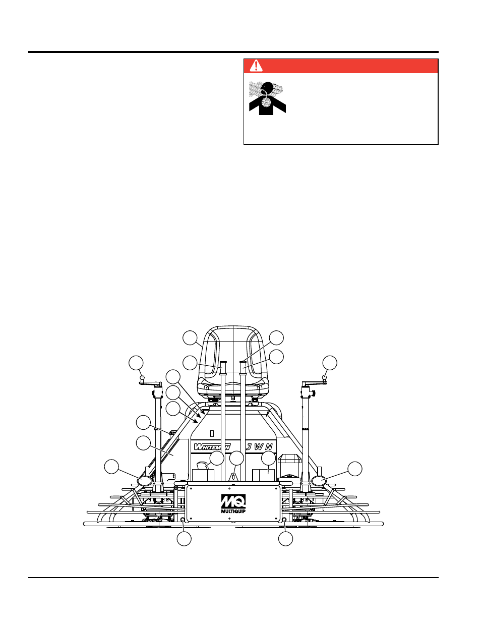
cOMpOnentS
1.
Seat — Engine will not start unless operator is seated.
2.
Steering Control Levers — Directs the unit forward,
reverse, left, or right.
3.
Retardant Spray Control Button — Sprays retardant
through the nozzle at the front of the machine.
4.
Twin pitch Control — Both pitch towers are linked
together. One crank may be turned to adjust the blade
pitch simultaneously or individually controlled for each
set of blades. Turn the crank as marked on its top
surface to increase or decrease blade pitch.
5.
Light Switch — Turns on three halogen lights. Two
in front, one in rear.
6.
Ignition Switch — With key inserted, turn clockwise
to start engine.
7.
Hour meter — Indicates number of hours the engine has run.
8.
Choke Control Lever — In cold weather pull this
lever to start engine. After engine warms push knob
all the way in.
9.
Fuel gauge/Filler Cap — Indicates the amount of fuel
in the fuel tank. Remove this cap to add fuel.
10.
Fuel Tank — Holds 5 gallons of unleaded gasoline.
11.
Left Foot Riser — Operator foot rest pedal.
12.
Spray Nozzle — Spray nozzle for retardant.
13.
Right Foot pedal — Controls blade speed. Slow blade
speed is accomplished by slightly depressing the foot
pedal. Maximum blade speed is accomplished by fully
depressing the foot pedal.
14.
ez- mover Boss — Front attachment point for EZ
Mover. Used to move the trowel.
15.
Right Front Light — 12 volt halogen lights, used for
night operations.
16.
Left Front Light — 12 volt halogen lights, used for
night operations.
DaNgeR
Add fuel to the tank only when the engine
is stopped and has had an opportunity to
cool down. In the event of a fuel spill,
DO
NOT attempt to start the engine until the
fuel residue has been completely wiped up
and the area surrounding the engine is dry.
Figure 2. Components – Front
4
9
10
15
11
14
14
4
6
7
8
1
2
2
16
3
12
13