Operation – Multiquip LS-300 User Manual
Page 30
PAGE 30 — MAYCO LS300 CONCRETE PUMP • OPERATION AND PARTS MANUAL — REV. #4 (06/21/10)
OPERATION
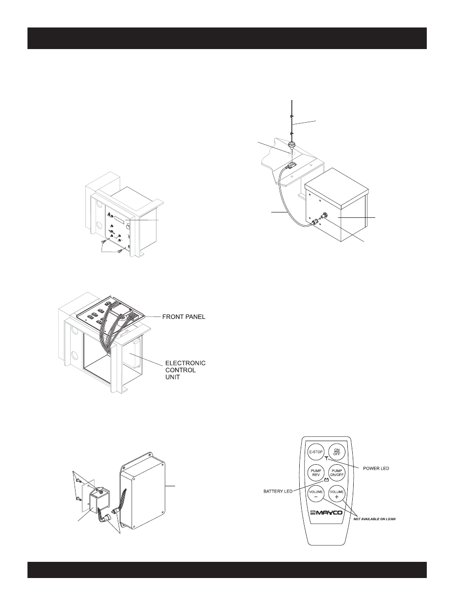
Figure 37. Radio Remote Control
REMOTE CONTROL (OPTIONAL)
The LS300 Concrete Pump has a remote control feature
that allows the pump to be remotely controlled. If desired,
the pump can be operated via a receiver/transmitter (radio)
or a hardwire method, which utilizes a 25-ft. extension cable.
Contact MQ Sales Department to order remote control.
Radio Remote Control
Installation of the Radio Remote Control Assembly
1. Remove the two screws on the digital control panel of
the pump. See Figure 33.
2. Tilt and slowly pull out the control panel and place on
top of box to gain access inside the box. See Figure 34.
3. Install the wireless remote module with the 2 screws
and nuts provided inside the control panel. Connect the
3-wire connector from the wireless remote module to
the electronic control unit. See Figure 35.
Radio Remote Control Buttons Operation
The pumping operation can be performed by radio remote
control (Figure 37). Before using remote control, move the
Pumping Control Switch on the control box to the REMOTE
position. The buttons on the remote control have the following
functions.
ON/OFF - Turns the power on or off. When power is on the
power LED lights red. If the battery LED turns red, 9V battery
needs to be replaced.
E-STOP - Turns off the pump completely in an emergency.
PUMP ON/OFF - Starts and stops the forward pumping.
PUMP REV - momentarily pumps in reverse direction.
Figure 33. Removing Screws from Control Panel
EMERGEN
C
Y
S
T
O
P
OF
F
ON
IG
NIT
IO
N
RE
M
OT
E
CO
NT
RO
L
FL
OW
DIR
EC
TIO
N
VO
LU
M
E
LO
CA
L
FO
RWA
RD
AU
TO
M
AT
IC
JO
G
RE
SE
T
SE
T
DE
CR
EA
SE
IN
CR
EA
SE
SC
RO
LL
JO
G
“A”
CY
LIN
DE
R
ST
RO
KE
JO
G
“B”
RE
VE
RS
E
CE
NT
ER
OF
F
RE
M
OT
E
ST
AR
T
REMOVE 2 SCREWS
CONTROL BOX
Figure 34. Pulling Out Control Panel
4. Reinstall the control panel and tighten the 2 screws.
5. On the top of the unit, to the right of the control box
(Figure 36), hammer out the knock-out hole and install
the remote antenna.
6. Connect the antenna cable to the connector on the rear
of the control box (Figure 36).
Figure 35. Installing Remote Control Module
Figure 36. Antenna Installation
ANTENNA
KNOCK-OUT
HOLE
ANTENNA
CONNECTOR
CABLE
CONTROL BOX
CONNECTOR
REAR OF
CONTROL BOX
SCREWS AND NUTS
WIRELESS
REMOTE
MODULE
CONNECTOR
ELECTRONIC
CONTROL
UNIT