Digital readout screen – Multiquip LS-300 User Manual
Page 21
MAYCO LS300 CONCRETE PUMP • OPERATION AND PARTS MANUAL — REV. #4 (06/21/10) — PAGE 21
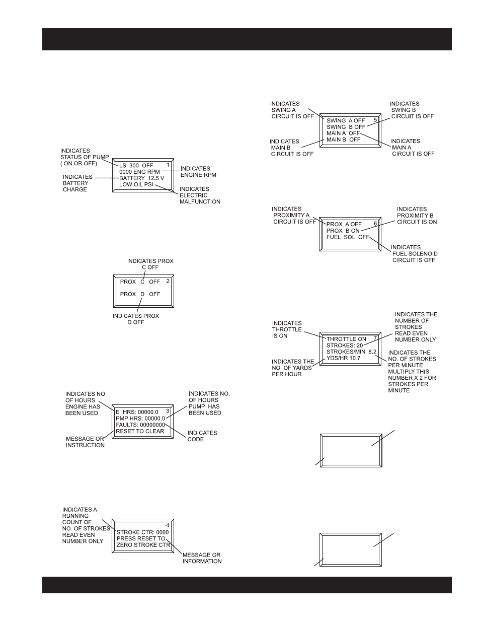
DIGITAL READOUT SCREEN
PRIMARY SCREEN
Screen 1
Indicates the various modes of the switch settings.
Monitors engine RPM - Idle speed 900, High speed 2550.
Battery charge indicator - Normal charge 13+ volts.
Indicates electrical malfunction - Refer to Troubleshooting
section.
SECONDARY SCREENS
Screen 2
Displays the status of the shuttle cylinder proximity switches.
Screen 3
Displays the number of hours the engine and pump have
been used and the fault codes the pump has registered. All
three indicators can be reset to zero by the RESET switch
on the control panel.
Screen 4
Displays the number of strokes the main hydraulic cylinders
have gone through. This indicator can be reset to zero by
the RESET switch on the control panel.
Screen 5
Displays the ON/OFF electrical signal status of the various
12 volt solenoids (Swing A circuit, Main A circuit, Main B
circuit).
Screen 6
Displays the ON/OFF electrical signal status for the
Proximity Switch A, Proximity Switch B, Engine Fuel
Solenoid, and Unloader Solenoid.
Screen 7
Displays the number of times the main hydraulic cylinders
stroke and the yards per hour output. This indicator can be
reset to zero by the RESET switch on the control panel.
Screen 8
Displays the electrical status of the engine fuel solenoid. To
test the 12-Volt solenoid status, activate with the RESET
switch on the control panel.
INSTRUCTION
OR MESSAGE
INDICATES THE
FUEL SOLENOID
IS OFF
TO TEST FUEL
SOL PRESS RESET
FUEL SOL OFF
8
Screen 9
Displays the communication status of the (optional) radio
remote control. To activate a new remote control connection,
use the reset switch on the control panel.
INDICATES
THAT RADIO
REMOTE IS ON
IINSTRUCTION
OR MESSAGE
RADIO ADDRESS
COMMUNICATING
PRESS RESET TO
LEARN A NEW ONE
9