Crosshead clamping bolt torque values, Move the crosshead hydraulically – MTS Landmark Tabletop User Manual
Page 63
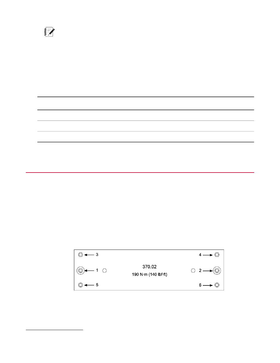
Note:
Use the same sequence when you loosen the bolts.
Crosshead Clamping Bolt Torque Values
The following table includes values for crosshead clamping bolt torques for each step in the manual clamping
procedure.
Torque Values
Step 4
1
Step 3
Step 2
Step 1
Load Unit
190 N·m (140 lbf·ft)
190 N·m (140 lbf·ft)
171 N·m (126 lbf·ft)
20 N·m (15 lbf·ft)
370.02
190 N·m (140 lbf·ft)
190 N·m (140 lbf·ft)
171 N·m (126 lbf·ft)
20 N·m (15 lbf·ft)
370.10
271 N·m (200 lbf·ft)
271 N·m (200 lbf·ft)
244 N·m (180 lbf·ft)
20 N·m (15 lbf·ft)
370.25
Move the Crosshead Hydraulically
This procedure describes how to position a crosshead for a Series 370 Load Unit equipped with hydraulic
crosshead lifts.
1. Pressurize the lift actuators. The crosshead may have shifted position while hydraulic pressure was turned
off.
Briefly turn the Crosshead Lift Control to the lift crosshead position to apply a slight upward pressure to
the crosshead.
Then return the lift control to the stop position "O."
2. Unclamp the crosshead. Loosen the four bolts that clamp the crosshead to the columns.
3. Use the Crosshead Lift Control to move the crosshead to a point where you can install the specimen
(or specimen fixture) into the upper grip or fixture without obstruction.
Set the control to the stop position "O" before proceeding.
1
This step ensures uniform tightness.
MTS Landmark™ Tabletop Load Units Product Information 63
Operation