MTS DCPD Measurement System User Manual
Page 34
The following sequence is a guideline for using the foil specimen in validation system operation. The
sequence assumes the DCPD unit has been connected to the controller and that the controller has been
set up for DCPD operation.
1. With the DCPD unit power off (I/0 switch on the back panel to 0), ensure the DCPD unit is properly
connected to the controller and the controller has been set up for DCPD operation as defined in the
Installation section.
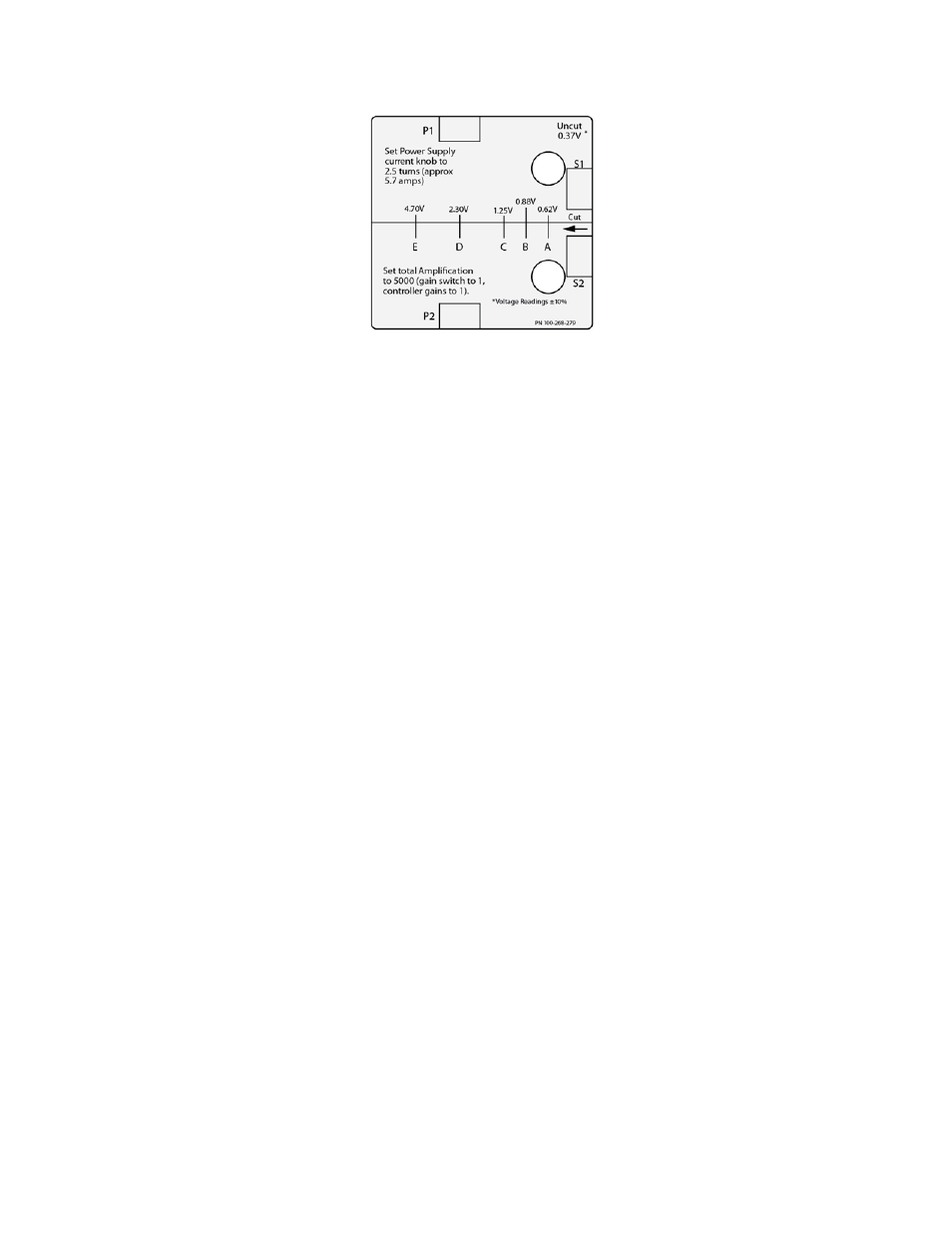
2. With the DCPD unit power off, connect the cables to the foil specimen as shown in the above illustration.
3. Switch the Remote/Local switch to Local.
4. Turn the Current Set adjustment to 250 (2.5 turns).
5. Switch the 1X/10X switch to the 1X position. Verify that there is no additional gain (gain set to 1) on the
active or reference electronics (DUC or A/D).
6. Apply Power to the DCPD (I/0 switch on the back panel to I).
7. Use the digital output in Station Manager to turn the current on. The Green light on the front of the
DCPD unit should light up.
8. Observe the voltage reading and verify that it is close to 0.37 V (+/- 10%) on a meter or scope in Station
Manager.
9. Turn the digital output off in the Station Manager and verify the Red light is lit on the front of the DCPD
unit.
10. Disconnect the cable clips and cut the foil specimen to the first cut line (indicated by the letter "A" printed
on the foil specimen).
11. Connect the cable clips back onto the foil specimen. Try and get the clips as close a possible to the
original position.
12. Turn the digital output on in the Station Manager and verify the green light is lit on the front of the DCPD
unit.
13. Observe the voltage reading and verify that it is close to 0.62 V (+/- 10%) on a meter or scope in Station
Manager.
14. Repeat steps 9 through 13 making subsequent cuts to the next cut line and verifying the associated
voltage readings indicated on the foil specimen.
15. Verification of the voltage readings indicated on the foil specimen confirms the DCPD unit is functioning
properly.
34 | DCPD Measurement System
Installation