Corrugated – Metal Sales 7/8 Corrugated User Manual
Page 7
P7/8-7
7
/
8
" CORRUGATED
© Metal Sales Manufacturing Corporation/ Subject to change without notice/ Effective Date 9/11
800.406.7387 (Corporate Office) • www.metalsales.us.com
1. Section properties and allowable loads are calculated per AISI 2001 including 2004 Supplement.
2. Ixx and Sxx are effective section properties for deflection and bending
3. Allowable loads/spans are calculated considering bending, shear, combined bending and shear and deflection.
4. Allowable loads/spans calculations do not include consideration for web crippling, fastener / connection limitations or uplift testing.
5. Allowable loads/spans do not include a 1/3 stress increase.
6. Allowable loads for 24 ga. are based on ASTM E 330 test results attaching to 16 ga. girts
ALLOWABLE UNIFORM LIVE LOADS PSF
(3 or More Equal Spans)
2’ 3’ 4’ 5’ 6’ 7’ 2’ 3’ 4’ 5’ 6’ 7’
SECTION PROPERTIES
Bottom in Compression
Width
(in.)
Yield
KSI
34.67"
80
34.67"
50
34.67"
50
34.67"
33
26
Ga.
24
22
20
Sxx
In
3
/ft
Ixx
In
4
/ft
Weight
PSF
0.94
1.22
1.60
1.95
Top in Compression
Sxx
In
3
/ft
Ixx
In
4
/ft
0.0255 0.0580 0.0255 0.0580
386
156 66 34 20 8 386 156 66 34 20 8
0.0330
0.0744
0.0330
0.0744 175 151 127 102 78 30 175 151 127 102 78 30
0.0413 0.0956 0.0413 0.0955
530 241 107 55 32 13 530 241 107 55 32 13
0.0488 0.1146 0.0488 0.1146
419 191 108 64 37 16 419 191 108 64 37 16
Inward
Load
Outward
Load
Substructure
Coverage
Length
Fastener
Availability
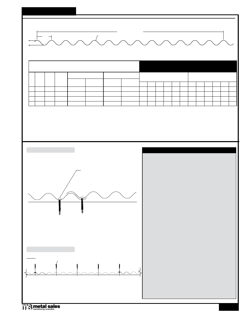
GENERAL INFORMATION
WALL ATTACHMENT
FASTENING PATTERN
7/8" Corrugated panel is designed to be utilized over open
structural framing but can easily be used with a solid substrate.
To avoid panel distortion use a properly aligned and uniform
substructure.
7/8" Corrugated panel has a coverage width of 34
2
/
3
"
Minimum factory cut length is 3'-0". Maximum recommended
panel length is 45'-0". Longer panels require additional
consideration in packaging, shipping, and erection. Please
consult Metal Sales for recommendations.
The fastener selection guide should be consulted for choosing
the proper fastener for specific applications. Quantity and type
of fastener must meet necessary loading and code requirements
NOTE: All panels are subject to surface distortion due to
improperly applied fasteners. Overdriven fasteners will cause
stress and induce oil canning across the face of the panel at or
near the point of attachment.
Finishes: Bare galvanized, MS Colorfast45
®
, PVDF, Weathering
Steel, and Acrylic Coated Galvalume
®
Gauges: 26ga, 24ga, 22ga, and 20ga
WALL
#12-14 Self Driller
2
2
/
3
"
34
2
/
3
" Coverage
7
/
8
"
C
s
eCTion
P
roPerTies
& g
eneral
i
nformaTion
(w
all
P
anel
)