Assembly – Meade Instruments LX850 User Manual
Page 17
connector is now ready to be inserted into the RS232
receptacle on the control panel labeled “StarLock.”
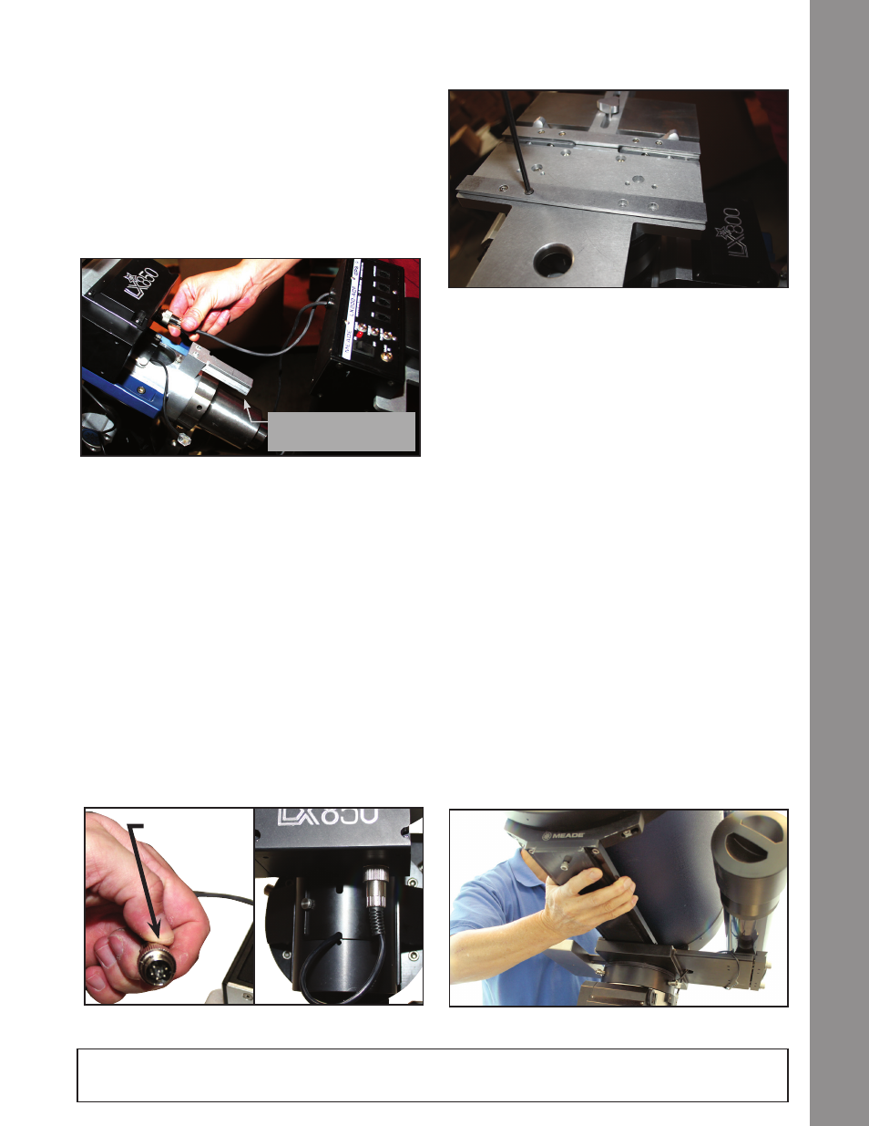
At this point you will need to reattach the Optical Tube
Saddle Plate. Reverse the steps outlined in the step
“Removing the Saddle” above.
Attach the Control Module
Take the control panel module out of the box that
contained the mount, and slide it on the mounting
rail at the rear end of the RA housing. Loosen the
two knurled set-screw knobs on the bottom side of
the control module and slide it on the rail, tightening
the same set-screw knobs. Insert the StarLock six-
pin connector into the receptacle labeled “StarLock”
(Page 10, Fig. 6a, H).
DEC and RA Connecting Cables
The connecting cables for the RA & DEC are attached
to the control panel module and can not be removed
from the module. The short cable connects directly
to the RA gearbox that is directly above the module.
Insert the DIN connector, observing and aligning the
orientation of the pins to match. Once the pins are
seated, secure by screwing the dedicated retaining
collar until firm
(Fig. 21). The longer cable connects
to the DEC gearbox and will need to be threaded
through the access port on the RA axis, directly above
the module
(Fig. 20). Using the cable pull tool feed
the cable through the raceway, watch for it through
the access port on the front of the RA axis
(Fig. 21).
Grasp it as it comes within reach, and feed through the
excess cable. Once it has been fed through, insert and
secure the connector to the DEC drive directly above
the access port
(Page 8, #21). Once the pins are
seated, secure by screwing the dedicated retaining
collar until firm.
Attach the Optical Tube
Assembly (OTA)
Note that there are two options for orientating the
dovetail rail and its location. As shipped from the
factory, dovetail rails are configured to receive a
standard Losmandy®-style dovetail. Meade LX850
OTAs are shipped with their dedicated dovetail plates
pre-attached to the tube. Depending on your OTA’s
Fig 22: Replace the saddle plate
Fig 23: Slide the OTA dovetail into the saddle plate
Fig 20: Connecting motor to control module.
Note Rail to attach
Telescope Control Module
17
Assembly
Note: Locking
collar
Fig 21: DIN Style Connector
NOTE: Remove the travel screw before attempting to focus the OTA. Failure to do so may result in damage
to the Crayford focusing mechanism.